
Otoscope Providing Low Obstruction Electronic Display

a technology of electronic display and otoscope, which is applied in the field of otoscope, can solve the problems of substantial blinding of internal reflection by mounted cameras and light sources, and achieve the effects of reducing the obstructive quality of the display, improving the ability to simultaneously view, and enhancing dexterity

Active Publication Date: 2018-05-10
WISCONSIN ALUMNI RES FOUND
View PDF9 Cites 42 Cited by
  • Summary
  • Abstract
  • Description
  • Claims
  • Application Information

AI Technical Summary

Benefits of technology

The present invention aims to improve the viewing experience and comfort of a clinician during an otoscopic examination. This is achieved by using a matching circular display that can be aligned with different orientations of the timpox, while minimizing the obstructive qualities of the display. Additionally, the invention provides a disposable, clean sheath for the tip-mounted camera and light source, which reduces the risk of blinding internal reflections and ensures a clean barrier between the otoscope and patient. The invention also offers a structure allowing the otoscope to be adapted to commonly available otoscope bases, providing flexibility and ease of use.

Problems solved by technology

Such tip-mounted cameras and light sources create substantial risk of blinding internal reflection when covered by a window.

Method used


Image

  • Otoscope Providing Low Obstruction Electronic Display
  • Otoscope Providing Low Obstruction Electronic Display
  • Otoscope Providing Low Obstruction Electronic Display

Examples


first embodiments

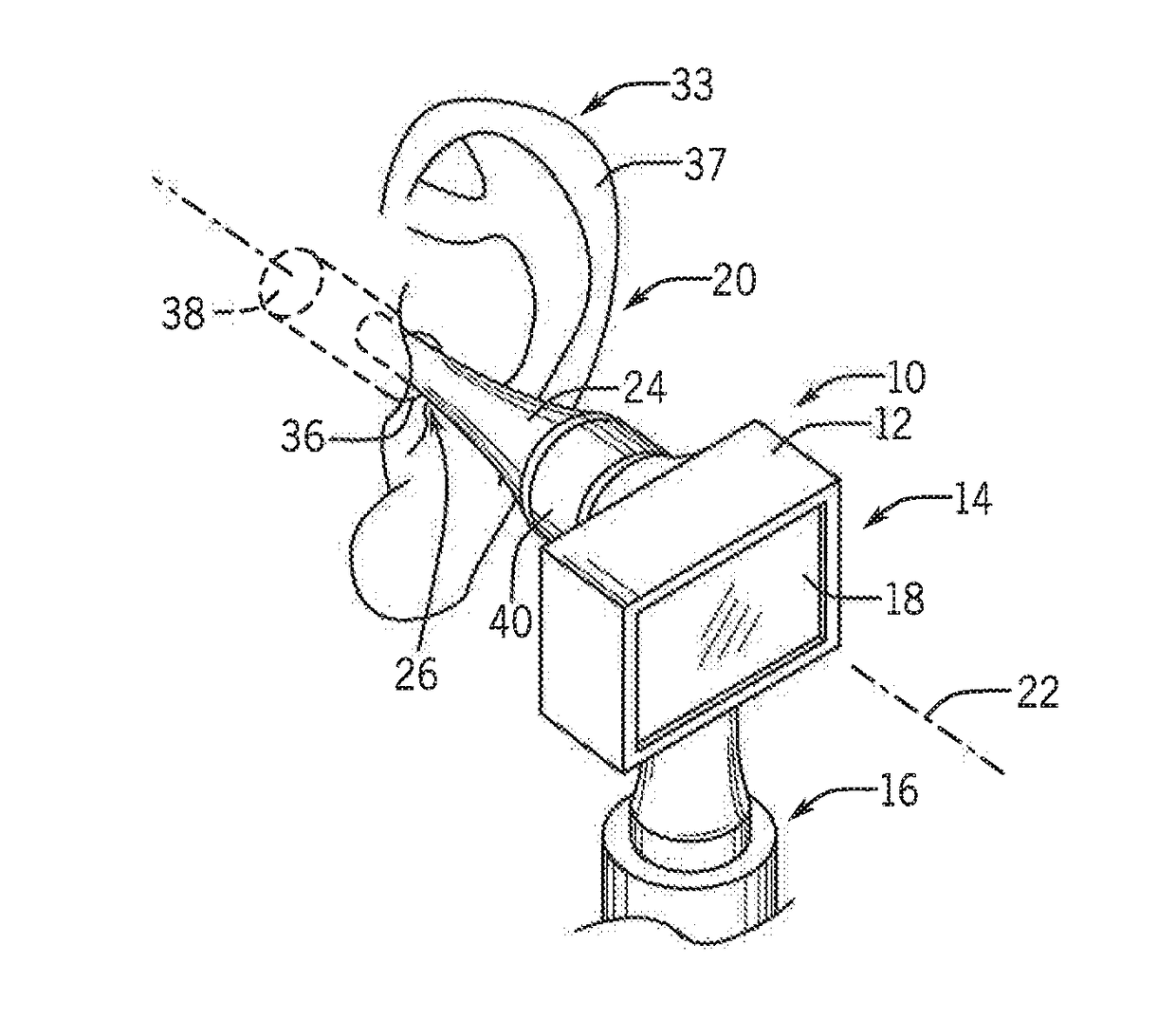
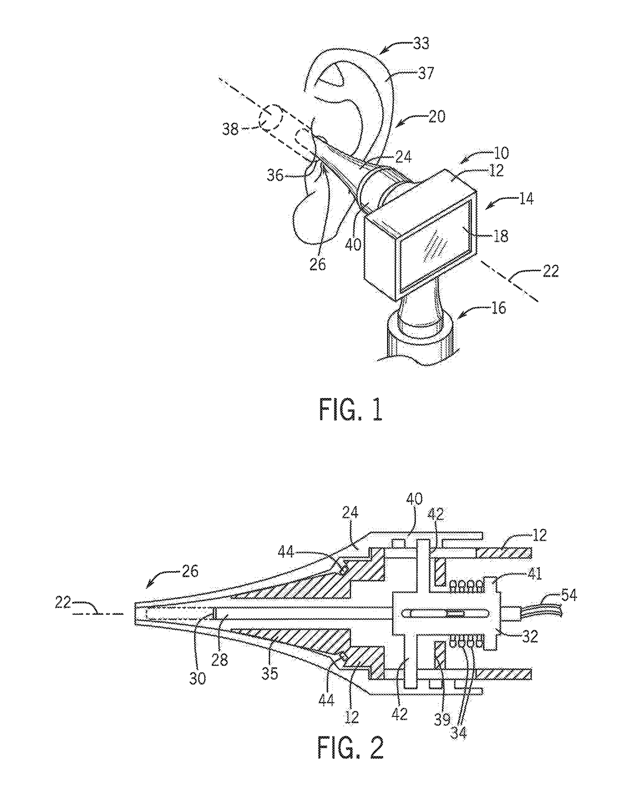
[0065]Referring now to FIG. 1, an otoscope 10 of the present invention may provide a housing 12 having a head portion 14 and a detachable grip portion 16. The grip portion 16 is sized to be grasped by the hand of a healthcare professional in the manner of a conventional otoscope with the grip portion 16 extending generally upward from the healthcare professional's hand to the head portion 14.

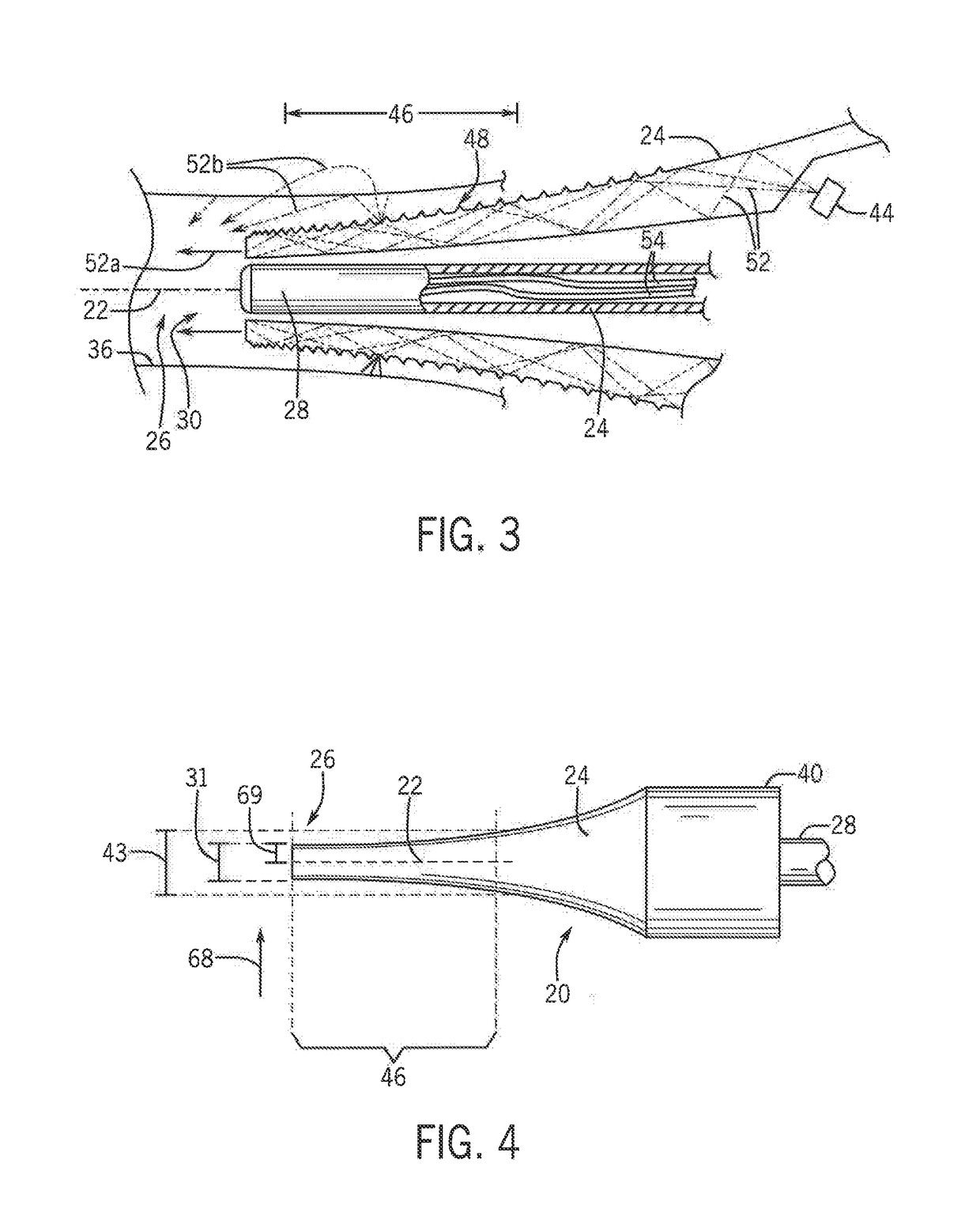
[0066]A front surface of the head portion 14 may provide for an electronic touchscreen display 18, for example, being a backlit three-color liquid crystal display (LCD) of a type known in the art having a touch surface and decoder, An elongate probe assembly 20 may extend from a rear face of the head portion 14 in a direction away from the display 18 along an axis 22 normal to the surface of the display 18. The probe assembly 20 may include a generally conical speculum 24 constructed at least in part of the transparent thermoplastic material to provide for light conducting properties as will be ...

second embodiments

[0086]Referring now to FIG. 7, the display 18 may be circular in outline having a diameter of approximately 1.5 inches and less than two inches and desirably less than 2.5 inches. The display 18 may be centered on the axis 22 having a viewable face perpendicular to that axis 22 so that the display 18 is subtended by a right circular cone 133 having its apex at the distal end of the cylindrical probe 28 and its base perpendicular to the axis 22. This subtending cone 133 may have a vertex angle 23 of less than 60 degrees and ideally less than 45 degrees to provide an improved ability by the healthcare professional to visualize the outer ear 33 (shown in FIG. 1) around the display 18 and the housing 12.

[0087]The grip portion 16 may include a downwardly extending grip collar 124 connecting the head portion 14 with a removable power handle 126 that may fit within the collar 124 and lock to the housing 12 with a quarter turn of the power handle 126. In this regard, the power handle may ha...


PUM


Abstract

An otoscope provides a circular display allowing a compact housing providing improved simultaneous viewing of the display and the patient's ear for improved positioning and stabilization of the otoscope. A recorded image may be rotationally corrected, and non-image data displayed on the screen may be rotationally corrected with the use of an inclinometer.

Description

CROSS REFERENCE TO RELATED APPLICATION[0001]This application is a continuation in part of U.S. application Ser. No. 14 / 749,945 filed Jun. 25, 2015, and hereby incorporated by reference.STATEMENT REGARDING FEDERALLY SPONSORED RESEARCH OR DEVELOPMENTBACKGROUND OF THE INVENTION[0002]The present invention relates to an otoscope for inspection of the ear and in particular to an otoscope employing an electronic camera insertable into the ear canal.[0003]An otoscope is a medical device allowing a healthcare professional to inspect the ear canal and tympanic membrane (eardrum). A simple otoscope provides for a hollow funnel-shaped speculum whose small end is inserted into the ear canal. The purpose of the funnel shape of the speculum is to provide a visual path to the tympanic membrane and to assist in controlling depth of insertion of the speculum. Modern otoscopes include an internal source of illumination directed down the speculum axis from a contained battery-operated lamp and may prov...

Claims


Application Information

Patent Timeline
IPC IPC(8): A61B1/227A61B1/00
CPCA61B1/227A61B1/00048A61B1/00052A61B1/00082A61B1/00094A61B1/015A61B1/00148
Inventor REBELLA, GREGBERBEE, JAMESHAMEDANI, AZITA
Owner WISCONSIN ALUMNI RES FOUND
Learn More