
Fiber-reinforced plastic and production method therefor

a fiber-reinforced plastic and production method technology, applied in the direction of coatings, liquid surface applicators, wind energy generation, etc., can solve the problems of low fluidity at the time of shaping, difficult to shape the fiber-reinforced plastic into a complicated shape such as a three-dimensional shape, and limited shape of the structural material thus produced, so as to achieve excellent mechanical properties and reduce variation. , the effect of excellent heat resistan

Active Publication Date: 2018-05-03
MITSUBISHI CHEM CORP
View PDF0 Cites 3 Cited by
  • Summary
  • Abstract
  • Description
  • Claims
  • Application Information

AI Technical Summary

Benefits of technology

[0041]The fiber-reinforced plastic of the present invention exhibits controllable isotropy or anisotropy in the mechanical properties, has excellent mechanical characteristics with less variation, has excellent heat resistance, and also has satisfactory fluidity at the time of shaping.
[0042]According to the method for producing a fiber-reinforced plastic of the present invention, a fiber-reinforced plastic which exhibits controllable isotropy or anisotropy in the mechanical characteristics, has excellent mechanical characteristics with less variation, has excellent heat resistance, and has satisfactory fluidity at the time of shaping, can be produced conveniently at low cost.

Problems solved by technology

However, in this fiber-reinforced plastic, since continuous reinforcing fibers are used, fluidity at the time of shaping is low, and it is difficult to shape the fiber-reinforcing plastic into a complicated shape such as a three-dimensional shape.
Therefore, in a case in which the fiber-reinforced plastic is used, the shape of the structural material thus produced is limited mainly to those shapes close to a planar shape.
However, in this method, since the prepreg pieces are dispersed by causing prepreg pieces to fly by means of air or by spreading prepreg pieces in a liquid fluid and settling the prepreg pieces, it is very difficult to disperse the prepreg pieces uniformly such that the fiber axis directions of the reinforcing fibers are in completely random directions.
However, in this method, it is difficult to obtain a fiber-reinforced plastic in which mechanical properties are satisfactorily isotropic, or anisotropies thereof are under control, and there is less variation in the mechanical properties.
Typically, mechanical properties of a simple resin substance tend to deteriorate at a temperature higher than or equal to the glass transition temperature of the resin.
Similarly, in the case of a fiber-reinforced plastic, mechanical properties tend to deteriorate at a temperature higher than or equal to the glass transition temperature of the matrix resin.
However, according to the method described above, in the process for integrating deposited prepreg pieces by heating, only molten matrix resin flows into the gaps between the deposited prepreg pieces.
Due to the effect of these resin-rich portions, a fiber-reinforced plastic obtainable by this method has a problem of inferior heat resistance.
However, a fiber-reinforced plastic obtainable by this method has a problem that in a case in which stress occurs in a direction that follows the slit shape, these slit parts serve as the starting points of breakage, and mechanical properties deteriorate.
Furthermore, since substantially only the resin exists in these slit parts, at a temperature higher than or equal to the glass transition temperature of the matrix resin, the fiber-reinforced plastic has a problem of inferior heat resistance, similarly to the method disclosed in Patent Document 1.
Therefore, the production process becomes complicated, with difficulty in control, and the production cost increases.
Therefore, similarly in this case, the lamination operation becomes complicated, with difficulty in control, and the production cost increases.
However, in a fiber-reinforced plastic obtainable by this method, since the reinforcing fibers are three-dimensionally entangled, fluidity at the time of shaping is very poor.
Furthermore, the production process is also very complicated, and is markedly disadvantageous in terms of cost.
However, when it is intended to impregnate reinforcing fibers that are subjected to papermaking at a high density as such with a matrix resin, since reinforcing fibers that are oriented in the thickness direction (direction of impregnation) in particular, among the reinforcing fibers that are three-dimensionally entangled, cope with the stress of the pressing force at the time of impregnation, pressure is not transferred to the resin, and it is very difficult to achieve impregnation.
Furthermore, even in a case in which the fiber length of the reinforcing fibers is long, since three-dimensional entanglement becomes strong, similarly impregnation becomes difficult.

Method used

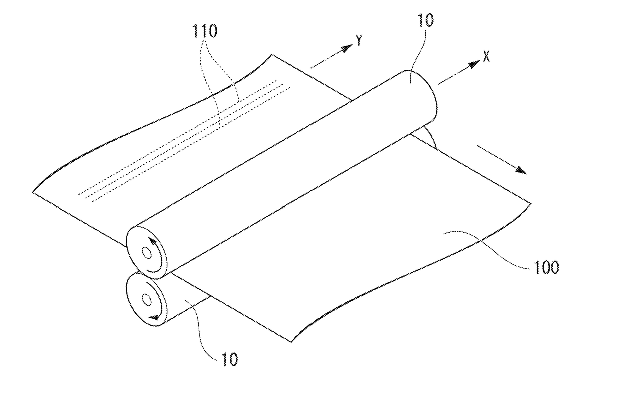
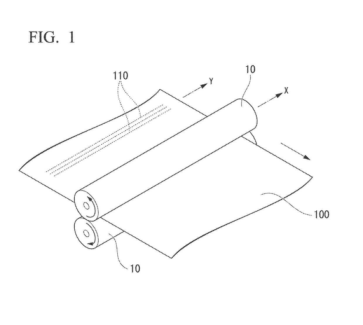

Image

  • Fiber-reinforced plastic and production method therefor
  • Fiber-reinforced plastic and production method therefor
  • Fiber-reinforced plastic and production method therefor

Examples


example of embodiments

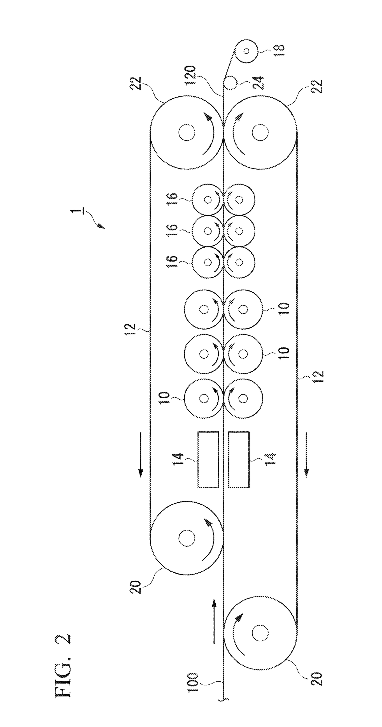
[0122]In the following description, an example of using a double belt-type heat press machine 1 illustrated in FIG. 2 (hereinafter, simply referred to as heat press machine 1) will be explained as an example of an embodiment of carrying out Step (ii-1) and Step (iii). Meanwhile, the embodiment of carrying out Step (ii) and Step (iii) is not limited to the embodiment of using the heat press machine 1.

[0123]The heat press machine 1 has a pair of belts 12 that cause a band-shaped material (A) 100 to travel in one direction in a state of having the material (A) vertically interposed therebetween; a pair of IR heaters 14 that preheat the material (A); three pairs of press rolls 10 in three rows, which vertically interpose the preheated material (A) 100 and press the material (A) 100; three pairs of warm water rolls 16 in three rows, which vertically interpose the pressed material (A) 100 and cool the material (A) 100; and a winding roll 18 that winds a fiber-reinforced plastic 120 that h...

production example 1

g Substrate-1

[0223]Carbon fibers (PYROFIL TR50S manufactured by Mitsubishi Rayon Co., Ltd., carbon fiber diameter: 7 μm) were arranged in parallel in one direction and in a planar form, and thus a fiber sheet having a basis weight of 72 g / m2 was obtained. Both surfaces of this fiber sheet were interposed between films each formed from an acid-modified polypropylene resin (MODIC P958V manufactured by Mitsubishi Chemical Corp., MFR50) and having a basis weight of 36 g / m2. These were subjected to heating and pressing by passing them through between calendar rolls several times, and the fiber sheet was impregnated with the resin. Thus, prepreg substrate-1 having a fiber volume percentage content (Vf) of 33% by volume and a thickness of 120 μm was produced.

production example 2

g Substrate-2

[0224]Carbon fibers (PYROFIL TR50S manufactured by Mitsubishi Rayon Co., Ltd.) were arranged in parallel in one direction and in a planar form, and thus a fiber sheet having a basis weight of 37 g / m2 was obtained. Both surfaces of this fiber sheet were interposed between films each formed from an acid-modified polypropylene resin (MODIC P958V manufactured by Mitsubishi Chemical Corp., MFR50) and having a basis weight of 45 g / m2. These were subjected to heating and pressing by passing them through between calendar rolls several times, and the fiber sheet was impregnated with the resin. Thus, prepreg substrate-2 having a fiber volume percentage content (Vf) of 17% by volume and a thickness of 120 μm was produced.


PUM

PropertyMeasurementUnit
angleaaaaaaaaaa
thicknessaaaaaaaaaa
lengthaaaaaaaaaa

Abstract

The purpose of the present invention is to obtain a fiber-reinforced plastic that is capable of controlling anisotropy, has excellent mechanical characteristics, has little variation, has excellent heat resistance, and has good fluidity during forming. A production method for fiber-reinforced plastic, having: a step in which a material (A) (100) including a prepreg base material is obtained, said prepreg base material having cuts therein and having a thermoplastic resin impregnated in reinforcing fibers (110) arranged in parallel in one direction; a step in which a pressurizing device is used that applies a substantially uniform pressure in a direction (X) orthogonal to the travel direction of the material (A) (100) and the material (A) (100) is caused to travel in the one direction and is pressurized while being heated to a prescribed temperature (T), an angle (.theta.) of −20-20 .degree. being formed between the orthogonal direction (X) and a fiber axial direction (Y) for the reinforcing fibers (110) of the prepreg base material; and a step in which the material (A) (100) pressurized by the pressurizing device is cooled and the fiber-reinforced plastic is obtained

Description

TECHNICAL FIELD[0001]The present invention relates to a fiber-reinforced plastic and a method for producing the same.[0002]The present application claims priority based on Japanese Patent Application No. 2014-026641, filed in Japan on Feb. 14, 2014, the disclosure of which is incorporated herein by reference.BACKGROUND ART[0003]In various fields related to aircraft members, automotive members, wind power generating windmill members, sports goods and the like, structural materials that have been shaped by stamping molding sheet-like fiber-reinforced plastics are widely used. Such a fiber-reinforced plastic is formed by, for example, laminating plural sheets of a prepreg substrate that is obtained by impregnating reinforcing fibers with a thermoplastic resin, and integrating the laminate.[0004]An example of the prepreg substrate is a product obtained by unidirectionally arranging continuous reinforcing fibers with a long fiber length in parallel, impregnating the arranged fibers with ...

Claims


Application Information

Patent Timeline
Patent Type & Authority Applications(United States)
IPC IPC(8): B29C70/50B29C70/88B29C70/46B29C70/48
CPCB29C70/887B29C70/50B29C70/46B29C70/48B29K2105/0881B29C70/504B29C43/46B29C2043/483B29K2105/0872B29K2105/105B29C35/10B29C2035/0822B29C43/18B29C43/28B29C43/34B29C2793/0036Y02E10/72B05D1/18B05D2256/00B29C2043/467
Inventor TOMIOKA, MASAOISHIKAWA, TAKESHIKOBAYASHI, TAKAYUKI
Owner MITSUBISHI CHEM CORP
Learn More