Device for collecting particles in an exhaled air flow

a technology of exhaled air and aerosol, which is applied in the direction of sensors, withdrawing sample devices, diagnostics, etc., can solve the problems of complex process of extracting collected particles from a polymer filter, lack of methods and devices for easy collection of aerosol particles,

Active Publication Date: 2018-05-03
MUNKPLAST
View PDF10 Cites 1 Cited by
  • Summary
  • Abstract
  • Description
  • Claims
  • Application Information

AI Technical Summary

Benefits of technology

The present invention is a device that collects a large number of aerosol particles in the exhaled breath without creating a high flow resistance. The device has partition walls that are designed to direct the airflow towards the surface of the device and create a labyrinth shaped flow path that allows the particles to separate from the air. This separation process is enhanced by a decrease in the cross-sectional area of the flow path, which increases the speed of the exhaled air. The device can be easily assembled with minimal effort, and it consists of two housing halves that are joined together using press fitting. This allows for the separation of heavier particles from the air, which results in a large number of aerosol particles being collected without the need for a separate pump.

Problems solved by technology

However, there is a lack of methods and devices for easy collection of said aerosol particles in exhaled breath.
Further, the impactor only collect some of all particles present in the exhaled breath.
However, extracting the collected particles from a polymer filter is a complex process requiring a large amount of analysis fluid to separate the particles from the filter fibres.

Method used


Image

  • Device for collecting particles in an exhaled air flow
  • Device for collecting particles in an exhaled air flow
  • Device for collecting particles in an exhaled air flow

Examples


Embodiment Construction

[0054]In the following, a detailed description of device according to the invention is presented. In the drawing figures, like reference numerals designate identical or corresponding elements throughout the several figures. It will be appreciated that these figures are for illustration only and are not in any way restricting the scope of the invention.

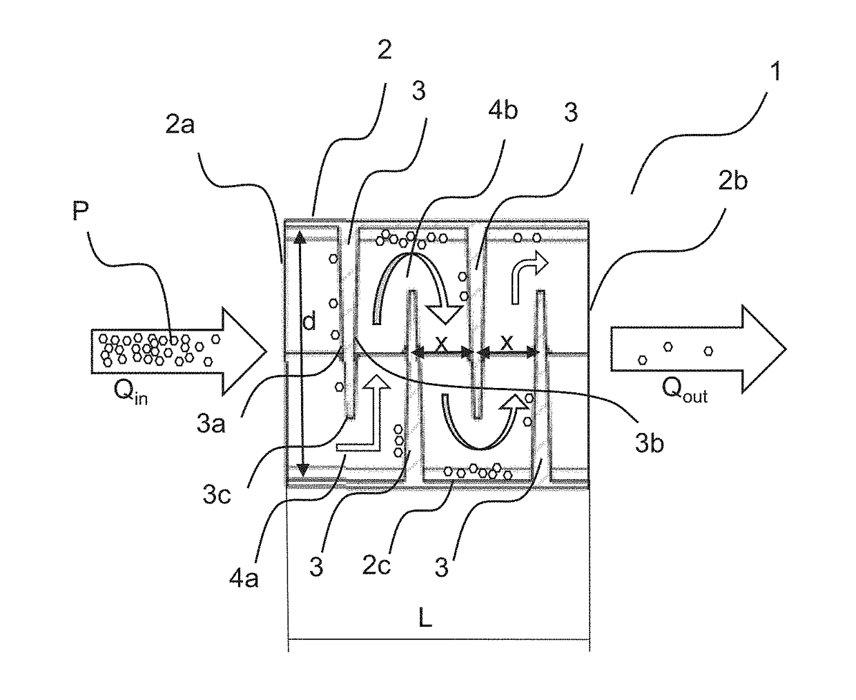
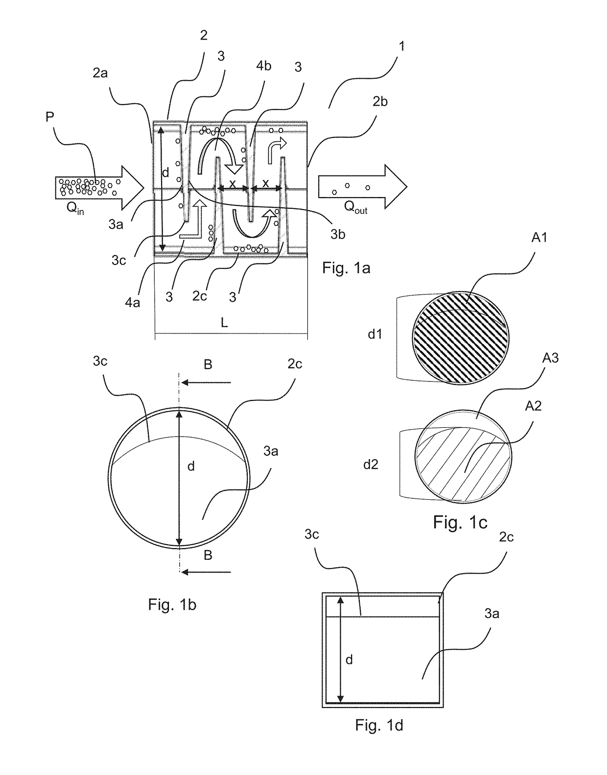
[0055]FIGS. 1a and 1b disclose an embodiment of the device 1 for collection particles in exhaled breath. FIG. 1a is a cut view taken at cut B-B in FIG. 1b and show the inside of the device 1. FIG. 1c visualizes the different cross section areas of the invention. FIG. 1d is another cut view of another embodiment of the device.

[0056]The device 1 comprises a housing 2 having an extension direction between a first end 2a with an inlet and a second end 2b with an outlet. The inlet is arranged to receive an exhaled airflow Qin comprising aerosol particles P from a subject, such as for example a person, and the outlet is arranged to transmit ...


PUM

PropertyMeasurementUnit
Timeaaaaaaaaaa
Timeaaaaaaaaaa
Fractionaaaaaaaaaa

Abstract

The invention relates to a device for collecting aerosol particles in an exhaled air flow. Said particles may be aerosol particles such as biomarkers or particles related to drugs or other substances formed or found in the alveoli of the lungs. Said device comprises a housing having an extension direction between a first end with an inlet arranged to receive an exhaled air flow and a second end with an outlet arranged to transmit the exhaled air flow and an inner cross section defined by inner walls of the housing and at least four first type partition walls, arranged in a direction essentially perpendicular to the walls, partly covering the inner cross section of the housing. Said first type partition walls protrude from opposite sides of the inner wall of the housing creating opposite openings between the first type partition walls and the housing inner wall, whereby said first type partition walls are arranged to create a labyrinth shaped flow path from said inlet to said outlet which is arranged to divert the air flowing from the inlet towards the outlet in a direction towards opposite inner wall of the housing so that said particles separate from the air flow and attach on the device and wherein the distance between two opposite first type partition walls is smaller than the distance between the inner walls of the housing.

Description

TECHNICAL FIELD[0001]The present invention relates generally to a device for collecting aerosol particles in an exhaled air flow. Said particles may be aerosol particles consisting mainly of surfactant formed or found in the alveoli of the lungs, such as biomarkers or exogenous compounds containing traces of drugs or other substances.BACKGROUND ART[0002]Human breath contains aerosol particles that are formed from the respiratory tract lining fluid covering the airways during normal breathing. Said particles have a size of between 0.1 and 2 μm, with an average size of between 0.3 and 0.8 μm. See article Characterization of Exhaled particles from the Healthy Human Lung, Journal of aerosol medicine and pulmonary drug delivery, Volume 23, Number 6, 2010 by Schwarz et al. The aerosol particles carry non-volatile components containing diagnostic information or biomarkers and are often studied as the breath condensate fraction. In this aerosol fraction, both lipids and peptides of endogeno...

Claims


Application Information

Patent Timeline
IPC IPC(8): A61B10/00A61B5/08A61B5/097G01N33/497G01N1/22
CPCA61B10/00A61B5/082A61B5/097G01N33/497G01N1/2247A61B2010/0087G01N2001/2244B01D45/08G01N1/2202A61B5/091A61B5/7405A61B90/03A61B5/742A61B2560/0431B01D45/16A61B2560/0285G01N2001/2223G01N1/2208A61B5/682
Inventor STAMBECK, PETER
Owner MUNKPLAST
Why Eureka
Try Eureka