Computer-implemented method for identifying zones of stasis and stenosis in blood vessels

a technology of stasis and stenosis, applied in the field of automatic identification of stasis and/or stenosis zones in blood vessel systems, can solve the problems of unproven benefits, insufficient prediction of heart attacks, invasive techniques that can provide more information, etc., and achieve the goal of obtaining the risk level of stasis in the zone more precisely, and improving the risk assessment effect of stasis

Active Publication Date: 2018-05-03
CORONARY TECH SARL
View PDF5 Cites 1 Cited by
  • Summary
  • Abstract
  • Description
  • Claims
  • Application Information

AI Technical Summary

Benefits of technology

[0017]Also D4 or D5 do not disclose that the outflow of the contrast agent from a zone is characterized, thereby allowing to obtain an improved risk level assessment for stasis in that zone. Hereby it can be noted that the outflow of the contrast agent refers to the end of the bolus of the contrast agent. I.e. in order to obtain an angiograph, an amount of contrast agent is injected in the vascular system. This amount of contrast agent forms at least one bolus which can be tracked. A bolus has a beginning and an end, which can be seen in an angiograph as clear changes in intensity level. When a bolus enters a zone, the intensity changes (typically decreases) drastically. Also when a bolus leaves a zone, the intensity changes (typically increases) drastically. The present invention basically focusses on the way the bolus leaves a zone, i.e. on the way the contrast agent flows out of such a zone. Hereby, the inventors have found that by characterizing how the contrast agent flows out the zone, a risk level for stasis in that zone can be obtained more precise and in an automated or semi-automated way.

Problems solved by technology

Currently there still exists a high rate of incidence of heart attacks.
A coronary angiogram is indeed a useful imaging technique but it cannot predict heart attacks well enough.
Techniques that can provide more information are invasive, more expensive or have an unproven benefit, e.g. thermography, virtual histology, intravascular ultrasound (IVUS), fractional flow reserve (FFR), palpography, etc.
Currently, there are no possibilities to quantify the shear stress in a zone of a blood vessel system in order to provide a risk level of stasis in that zone.

Method used


Image

  • Computer-implemented method for identifying zones of stasis and stenosis in blood vessels
  • Computer-implemented method for identifying zones of stasis and stenosis in blood vessels
  • Computer-implemented method for identifying zones of stasis and stenosis in blood vessels

Examples


example 1

[0056]In an embodiment, the present computer-implemented method for identifying a zone in a blood vessel system with a risk level for stasis comprises the following steps:

[0057]a) Data sourcing:

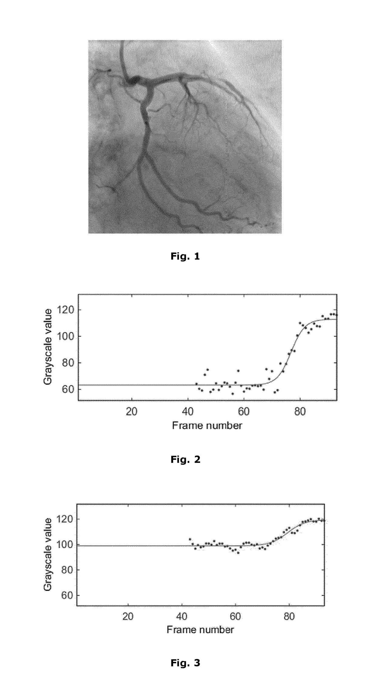
[0058]An angiogram movie consisting of multiple frames (e.g., FIG. 1) is provided in a DICOM (Digital Imaging and Communications in Medicine) format, and is imported and converted to a file format usable for processing by MATLAB®.

[0059]b) Background elimination:

[0060]In order to obtain the artery (=foreground) as it would appear without the background in the image, the background is subtracted from the original image. This involves estimating the background of each frame based on the maximal intensity value for each pixel in a time window around this frame. The highest intensity at each position is assumed to be the background intensity and is subtracted from the original image. Background suppression may result in a better artery segmentation (see below), due to the removal of background str...

example 2

[0081]In an embodiment, the present computer-implemented method is applied for the detection of stenosis, using the steps (a)-(c) of claim 1 and with the subsequent addition of steps comprising:

d1) Serving as inputs for the computer-implemented method, are:[0082]i. a blood vessel segment selected by the user[0083]ii. a segmentation mask

e1) For each point in the segment, the radius of the vessel is computed, as well as the stenosis percentage based on its neighbouring points

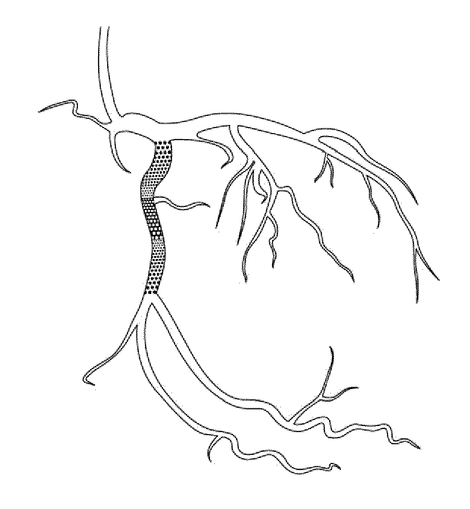
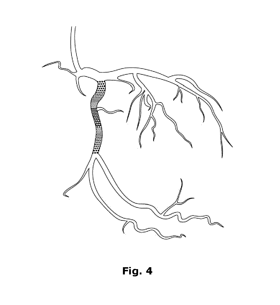
f1) Presentation of the results comprise a diagram whereby points above a certain stenosis percentage are indicated. For example, the stenosis percentage can be divided in the following classes: 95%. Optionally, the diagram can be accompanied with a warning should some points' percentages lie above a given percentage. These points will then also be indicated (e.g., using a specific colour) in one or more of the used angiogram images.

[0084]Overall, this method allows to better decide whether a treatment or a surgic...


PUM


Abstract

In a first aspect, the current invention concerns a computer-implemented method, system and computer program product for identifying a zone in a blood vessel system with a risk level for stasis, comprising the following steps: a) providing an angiogram of a blood vessel system, said angiogram comprising a time series of images of said blood vessel system, at least some of said images showing a contrast agent present in said blood vessel system; b) identifying at least one zone within said blood vessel system on a multitude of images of said time series; c) characterising variations in grey-scale intensity in said zone across at least part of said time series of images; d) characterising an outflow of said contrast agent from said zone on the basis of said variations in intensity in said zone; and e) providing a local risk level for stasis in said zone. In further aspects, the current invention also concerns a computer-implemented method, system and computer program product for identifying a zone in a blood vessel with a risk level for stenosis and stent malpositioning, and for measuring the coronary flow reserve (CFR).

Description

TECHNICAL FIELD[0001]The invention pertains to the technical field of the analysis of angiograms. This invention contributes to an improved automated identification of zones of stasis and / or stenosis in blood vessel systems.BACKGROUND[0002]Currently there still exists a high rate of incidence of heart attacks. Angiography, as classically performed by interventional cardiologists or radiologists using a catheter-based, minimally invasive technique, is based on acquiring images of arteries. Using a contrast dye or agent as a mimicking substance for blood, images depicting flow can thus be recorded and physicians may base their diagnosis and subsequently their therapy upon these data. A coronary angiogram is indeed a useful imaging technique but it cannot predict heart attacks well enough. Techniques that can provide more information are invasive, more expensive or have an unproven benefit, e.g. thermography, virtual histology, intravascular ultrasound (IVUS), fractional flow reserve (...

Claims


Application Information

Patent Timeline
Patent Type & Authority Applications(United States)
IPC IPC(8): A61B5/0275A61B6/00G06T7/00G16H50/30
CPCA61B5/0275A61B6/481A61B6/504A61B6/487A61B6/507A61B6/5217G06T7/0016G16H50/30A61B6/463A61B6/486A61B6/5235G06T2207/10076G06T2207/30104
Inventor VAN LANGENHOVE, GLENN
Owner CORONARY TECH SARL
Why Eureka
Try Eureka