In-vehicle device, information processing system, and information processing method
a technology of information processing system and vehicle, applied in the direction of road vehicle traffic control, traffic control system, instruments, etc., can solve the problem that the risk level of overtaking operation cannot be correctly determined in some cases
- Summary
- Abstract
- Description
- Claims
- Application Information
AI Technical Summary
Benefits of technology
Problems solved by technology
Method used
Image
Examples
first embodiment
[0107]A flow of the process of the information processing method according to the first embodiment will be described.
Process 1 of In-Vehicle Device
[0108]FIG. 4 is a flowchart showing the flow of a risk level determination process (1) according to the first embodiment. The process in FIG. 4 shows an example of determination processing for determining the risk level of a predetermined lane change, which is executed by the in-vehicle device 110, while the vehicle 10 is traveling.
[0109]In step S401 (detection step), the lane change detection unit 303 of the in-vehicle device 110 executes detection processing for detecting a predetermined lane change. The predetermined lane change detection processing of the lane change detection unit 303 will be described later with reference to FIGS. 5A and 5B.
[0110]In step S402, the lane change detection unit 303 makes the processing branch according to whether or not a predetermined lane change has been detected in step S401. In a case where a predet...
second embodiment
[0187]In the first embodiment, the decision unit 306 of the in-vehicle device 110 decides the first risk level by comparing the acceleration of the vehicle 10 with one or more first threshold values. However, the acceleration of the vehicle 10 is an example of the information indicating the acceleration of the vehicle 10. For example, the decision unit 306 may decide the first risk level using vehicle information relevant to the acceleration of the vehicle 10, such as a change in the speed of the vehicle 10 or the brake pressure.
[0188]In the second embodiment, an example of processing in which the decision unit 306 decides the first risk level by comparing the brake pressure of the vehicle 10 with one or more first threshold values will be described.
[0189]FIG. 12 is a flowchart showing the flow of a risk level determination process according to the second embodiment. Since the processing of steps S401 and S402 in the process shown in FIG. 12 is the same as the processing shown in FI...
third embodiment
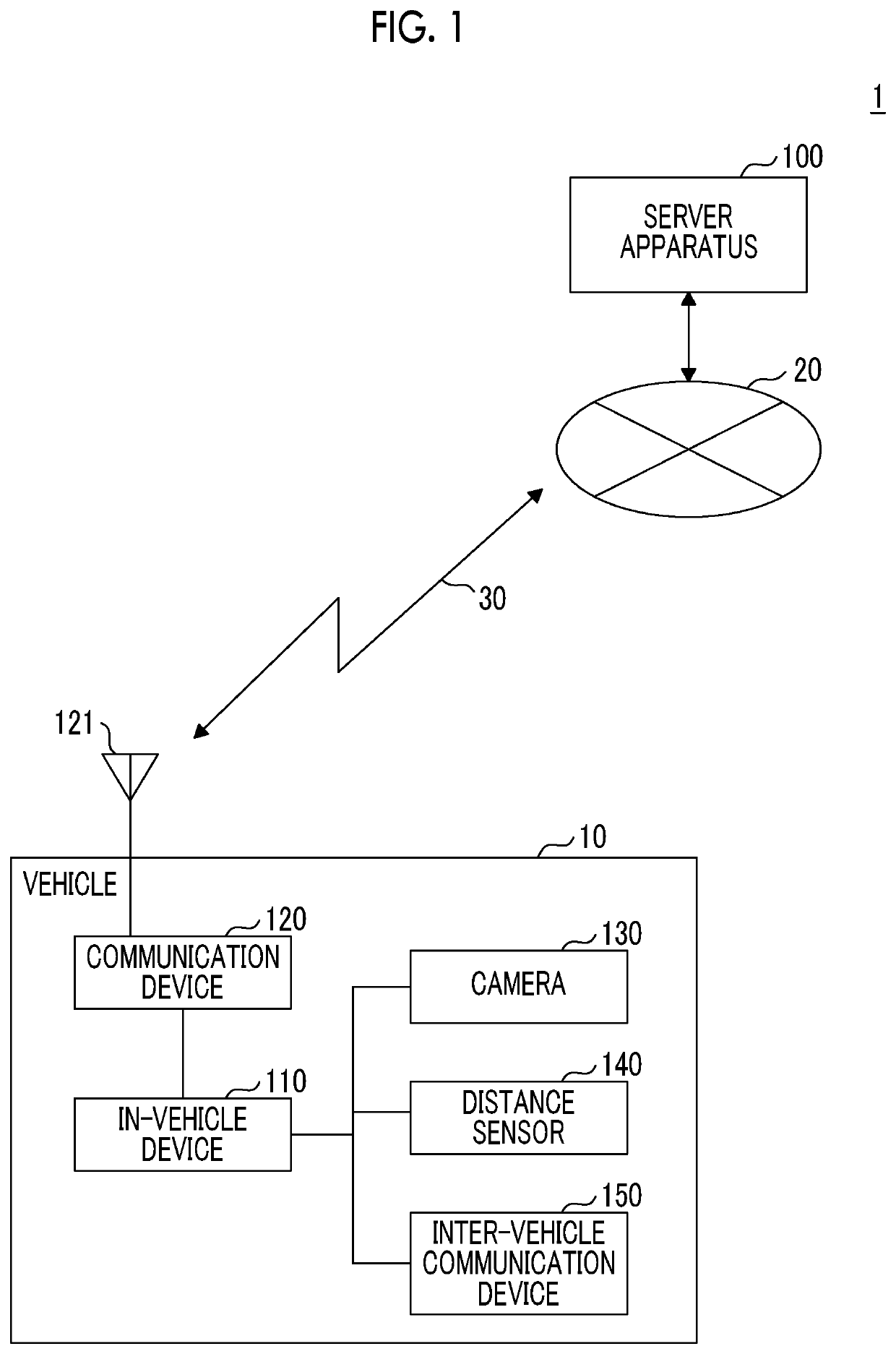
[0196]In the first embodiment, the in-vehicle device 110 detects other vehicles around the vehicle 10 using the image data obtained by imaging the periphery of the vehicle 10 with the camera 130. However, the disclosure is not limited thereto, and the in-vehicle device 110 may detect other vehicles around the vehicle 10 using the distance sensor 140, the inter-vehicle communication device 150, or the like.
[0197]Instead of the acceleration of the vehicle 10, the in-vehicle device 110 may determine the risk level of a predetermined lane change by comparing information indicating the distance between the vehicle 10 and another vehicle with one or more threshold values (second threshold value).
Functional Configuration
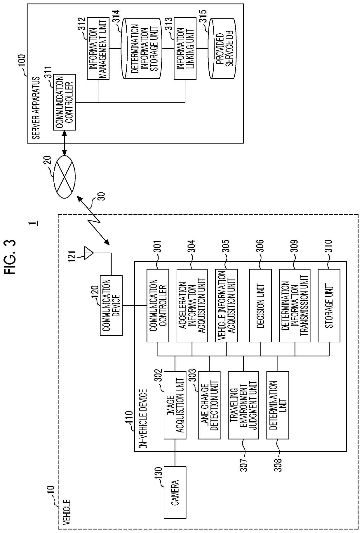
[0198]FIG. 13 is a diagram showing an example of the functional configuration of the information processing system according to the third embodiment. The in-vehicle device 110 according to the third embodiment has a distance information acquisition unit 1301 in addition to ...
PUM
 Abstract
Description
Claims
Application Information
 - R&D
- Intellectual Property
- Life Sciences
- Materials
- Tech Scout
- Unparalleled Data Quality
- Higher Quality Content
- 60% Fewer Hallucinations
Browse by: Latest US Patents, China's latest patents, Technical Efficacy Thesaurus, Application Domain, Technology Topic, Popular Technical Reports.
© 2025 PatSnap. All rights reserved.Legal|Privacy policy|Modern Slavery Act Transparency Statement|Sitemap|About US| Contact US: help@patsnap.com


