Connector

a technology of connectors and connectors, applied in the direction of couplings/cases, coupling device connections, electrical devices, etc., can solve the problems of connectors not meeting waterproof performance, product defects, and packing cracking, and achieve the effect of high rigidity, increased force to tightly fit the packing to the fitting portion, and waterproof performan

Active Publication Date: 2018-04-26
YAZAKI CORP
View PDF4 Cites 0 Cited by
  • Summary
  • Abstract
  • Description
  • Claims
  • Application Information

AI Technical Summary

Benefits of technology

[0015]In the connector having the configuration of (1), the notch portion is provided in a part of the resin ring portion that is locked to the engagement portion (locking arm) provided in the housing. As a result, the frame strength of the resin ring portion is weakened. In a case where the packing is mounted in the fitting portion of the housing, when the elastic member of the main body is compressed between the resin ring portion and the fitting portion, the notch portion extends due to the reaction force, and the resin ring portion extends (that is, the diameter thereof increases) in a direction opposite to a surface thereof tightly fitted to the fitting portion. As a result, the amount by which the elastic member of the main body is displaced from the space between the resin ring portion and the fitting portion to the distal end side is suppressed. Accordingly, the rising of the distal end side of the packing is prevented from occurring when the elastic member of the main body moves from the space between the resin ring portion and the fitting portion to the distal end side.
[0017]In the connector having the configuration of (2), in the resin ring portion of the packing, the notch portion is provided in the internal corner portion of the polygon. As a result, the diameter of the resin ring portion can be effectively increased as compared to a case where the notch portion is provided in a side portion of the polygon.
[0019]In the connector having the configuration of (3), the tapered thick portion is provided at the distal end of the main body of the packing. As a result, in the main body, the rigidity of the distal end is higher than that of the other portions. By providing the tapered thick portion having high rigidity at the distal end, when the packing is mounted on the fitting portion of the housing, a force to tightly fit the packing to the fitting portion is increased. As a result, even when a part of the elastic member of the main body is displaced from the space between the resin ring portion and the fitting portion to the distal end side, the separation of the distal end side from the outer periphery of the fitting portion is restricted, and the tightly fitted state is maintained. Accordingly, the rising of the distal end side of the packing prevented from occurring when the elastic member of the main body moves from the space between the resin ring portion and the fitting portion to the distal end side.
[0020]In the connector according to the present invention, a problem such as biting of the packing during fitting to another connector can be solved, and waterproof performance can be secured without any change in the number of parts and configuration.

Problems solved by technology

However, in the connector including the packing in which the resin ring portion is provided at the base end of the packing main body in order to retain the packing in the fitting portion of the housing as described above, there may be a problem such as biting of the packing during fitting to a counterpart connector.
When the connector fitting work is completed in a state where the packing is bitten, the connector cannot satisfy waterproof performance may have a product defect.

Method used


Image

  • Connector
  • Connector
  • Connector

Examples


first embodiment

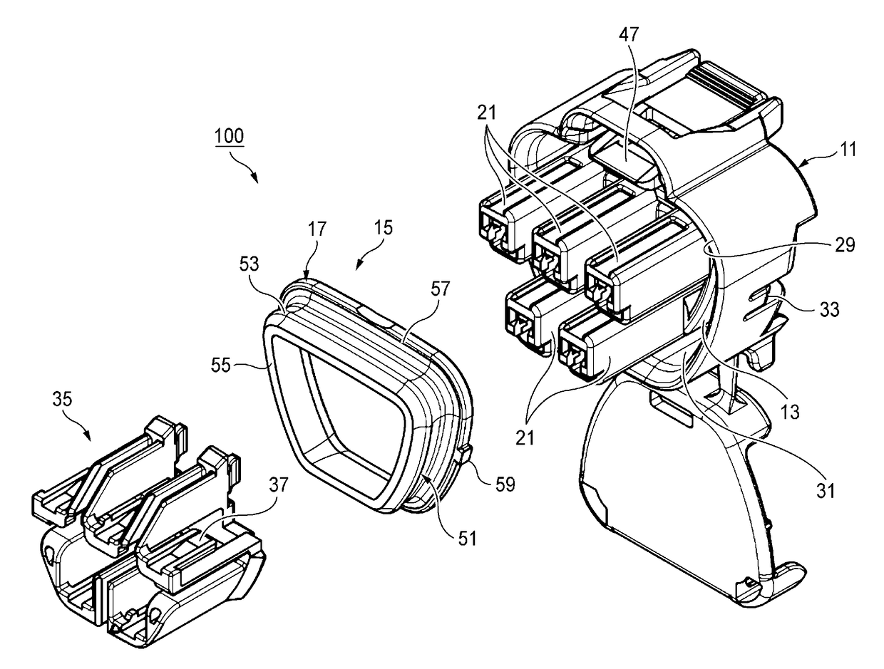
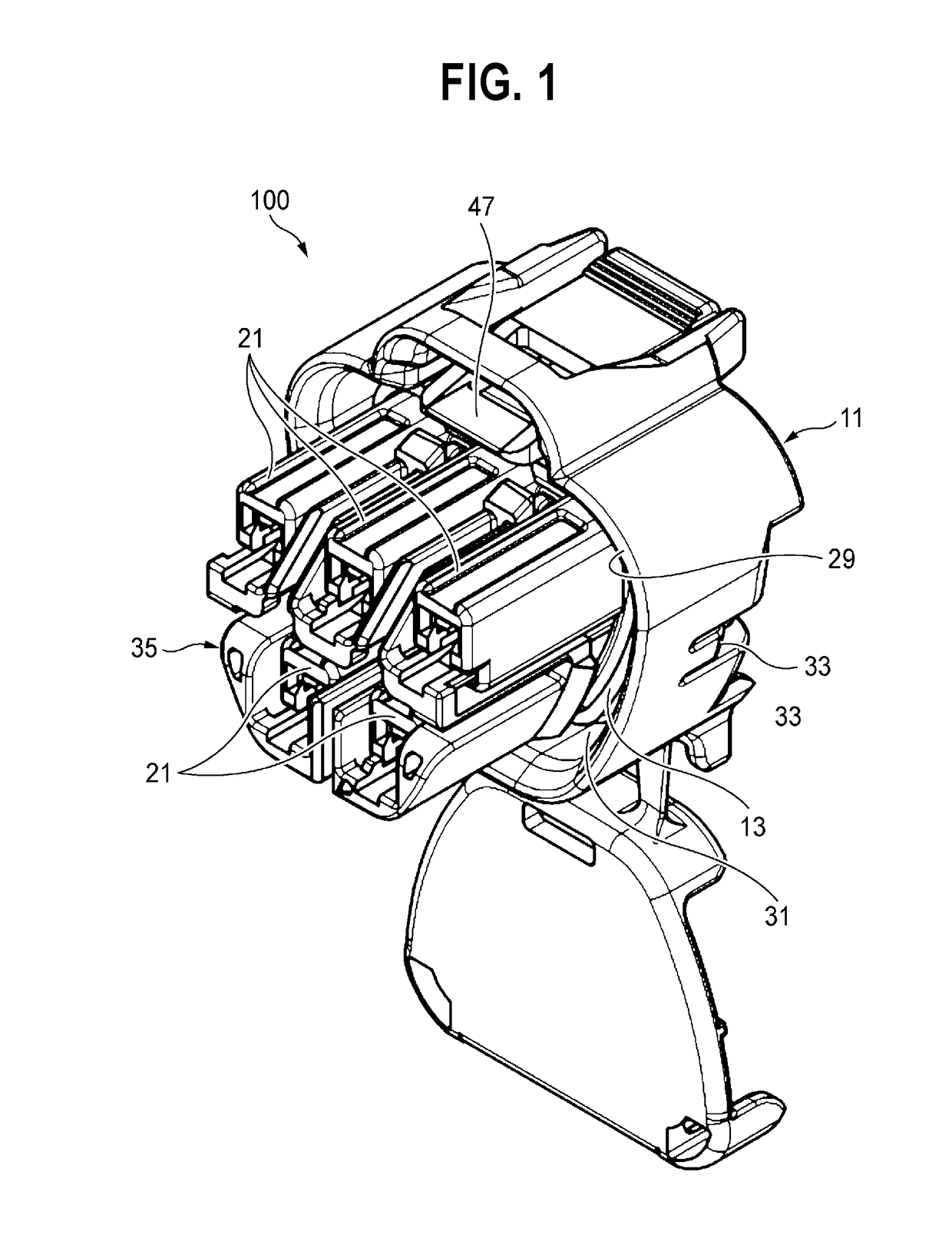
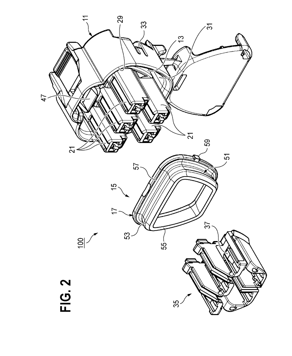
[0040]FIG. 1 is a perspective view illustrating a connector according to a first embodiment of the present invention, and FIG. 2 is an exploded perspective view illustrating the connector illustrated in FIG. 1. In this specification, a distal end side of a connector refers to a side where a counterpart connector is fitted.

[0041]A connector 100 according to the first embodiment can be used for, for example, a fuel tank of an automobile. The connector 100 provided in a wire harness of a floor mainly includes: a housing 11 that includes a fitting portion 13; and a packing 15 that is externally inserted to an outer periphery of the fitting portion 13.

[0042]The housing 11 is formed of, for example, resin such as plastic. This housing 11 includes the fitting portion 13 in which the outer periphery forms a cylindrical side surface. Plural terminal accommodation chambers 21 (in the embodiment, five) protrude from the fitting portion 13 to the distal end side.

[0043]In each of the terminal ac...

second embodiment

[0073]Next, a connector according to a second embodiment of the present invention will be described. In the second embodiment, the same members and portions as those illustrated in FIGS. 1 to 12D are represented by the same reference numerals, and the description thereof will not be repeated.

[0074]FIG. 13 is an exploded perspective view illustrating a connector 200 according to the second embodiment of the present invention.

[0075]The connector 200 according to the second embodiment is characterized in that it includes a main body 51A of a packing 67. The other configurations are the same as those of the connector 100 according to the first embodiment.

[0076]FIG. 14 is a perspective view illustrating the packing 67 illustrated in FIG. 13.

[0077]FIG. 15A a front view illustrating the packing 15 according to the first embodiment in which a tapered thick portion 69 is not provided at the distal end 55, FIG. 15B is a cross-sectional view taken along line C-C of FIG. 15A, and FIG. 15C is an...


PUM


Abstract

According an aspect of the invention, a connector includes a housing that includes a fitting portion having an outer periphery to which a cylindrical counterpart fitting portion of a counterpart connector is loosely fitted, a ring-shaped packing that includes a main body that is formed of an elastic member and is externally inserted in a tightly fitted manner to the outer periphery of the fitting portion so as to water-tightly seal a space between the fitting portion and the counterpart fitting portion, a ring-shaped resin ring portion that is provided at a base end of the packing, is formed of resin having a higher rigidity than the main body, and is locked to an engagement portion provided in the housing, and a notch portion that is provided in a part of an inner periphery of the resin ring portion.

Description

CROSS REFERENCE TO RELATED APPLICATION[0001]This application is based on Japanese Patent Application No. 2016-208735 filed on Oct. 25, 2016, the contents of which are incorporated herein by reference.BACKGROUND OF THE INVENTION1. Technical Field[0002]The present invention relates to a connector.2. Background Art[0003]For example, as a connector used in a vehicle such as an automobile, a connector including a housing and a packing that is formed in a ring shape and is mounted in the housing is known, in which the packing waterproofs a space between the packing and a counterpart connector (for example, refer to JP-A-2014-96264).[0004]In the connector, the packing includes: a packing main body that has a ring shape and is formed of resin such as rubber; and a resin ring portion that protrudes in a ring shape from an outer peripheral surface at a base end of the packing main body and is formed of resin such as plastic having a higher rigidity than the packing main body.[0005]When the pa...

Claims


Application Information

Patent Timeline
Patent Type & Authority Applications(United States)
IPC IPC(8): H01R13/52H01R13/516
CPCH01R13/5219H01R13/5216H01R13/516H01R2107/00H01R2201/26H01R13/5202H01R13/5205
Inventor SUZUKI, SHOGOKAWASHIMA, KENICHI
Owner YAZAKI CORP
Why Eureka
Try Eureka