
Vacuum pump system

a vacuum pump and pump technology, applied in the direction of pump control, pump components, rotary/oscillating piston combinations for elastic fluids, etc., can solve the problems of unnecessarily high energy expenditure of the pump, negative effect on the service life of the components, and the pump becomes cold, so as to reduce the sound level of the pump system, reduce the noise emission, and reduce the load

Inactive Publication Date: 2018-04-26
LEYBOLD HERAEUS GMBH & CO KG
View PDF5 Cites 5 Cited by
  • Summary
  • Abstract
  • Description
  • Claims
  • Application Information

AI Technical Summary

Benefits of technology

The patent describes a vacuum pump system that has multiple vacuum pumps connected in parallel and in series during the pumping process. This allows for high suction capacity without any loss of time. The system also consumes less energy, leading to increased lifespan of parts and reduced costs for air-conditioning and cooling. It allows for leak detection and reduces noise levels. The system is also highly redundant, meaning that even if one pump fails, the process can still be continued. Additionally, the system improves CO2 footprint and reduces operating costs.

Problems solved by technology

Consequently, during an idle and / or during a hold period an unnecessarily high energy expenditure of the pump is required.
In this case it is disadvantageous that the pumps become cold which has a negative effect on the service life of the components.
Further, linings may stick together and block the rotors.
These solutions are disadvantageous because of the large number of additional pumps.
Moreover, very small auxiliary pumps, such as ejector pumps, for example, cannot reduce the outlet pressure of the backing pump rapidly enough for attaining adequate power savings during short idle and / or hold periods.
Further, the auxiliary pumps require energy for operation.
This solution is disadvantageous due to the additional purchase and operating costs as well as the space required for the auxiliary pumps.
An additional expenditure for the pump system according to the disclosure is merely limited to relatively small dimensioned pipelines and switchover means, for example valves, as well as modifications to a pump control unit.

Method used


Image

  • Vacuum pump system
  • Vacuum pump system
  • Vacuum pump system

Examples


Embodiment Construction

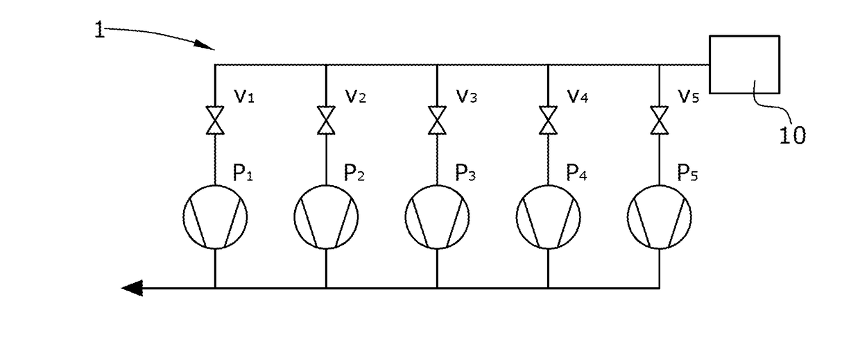
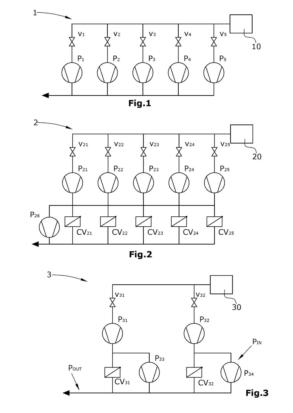
[0024]FIG. 1 shows a vacuum pump system 1 having a lock chamber 10 and parallel-connected pumps P1-P5 each of which is connected on its inlet side with the lock chamber. In addition, the vacuum pump system 1 comprises valves V1-V5, by means of which the connection from the pump inlets of the pumps P1-P5 to the lock chamber 10 can be disconnected. The illustrated vacuum pump system is known from prior art. During a pumping-out period the valves V1-V5 are open. The pumps P1-P5 consume a lot of power during the pumping-out period and operate at full speed. The pressure in the lock chamber decreases continuously.

[0025]During an idle period the valves V1-V5 are dosed and the pumps P1-P5 operate at full speed, wherein the power consumption essentially corresponds to that of the operation at a discharge pressure and continues to be relatively high. The pressure in the lock chamber is equal to a transfer pressure.

[0026]During a hold period the valves V1-V5 are open and the pumps P1-P5 opera...


PUM


Abstract

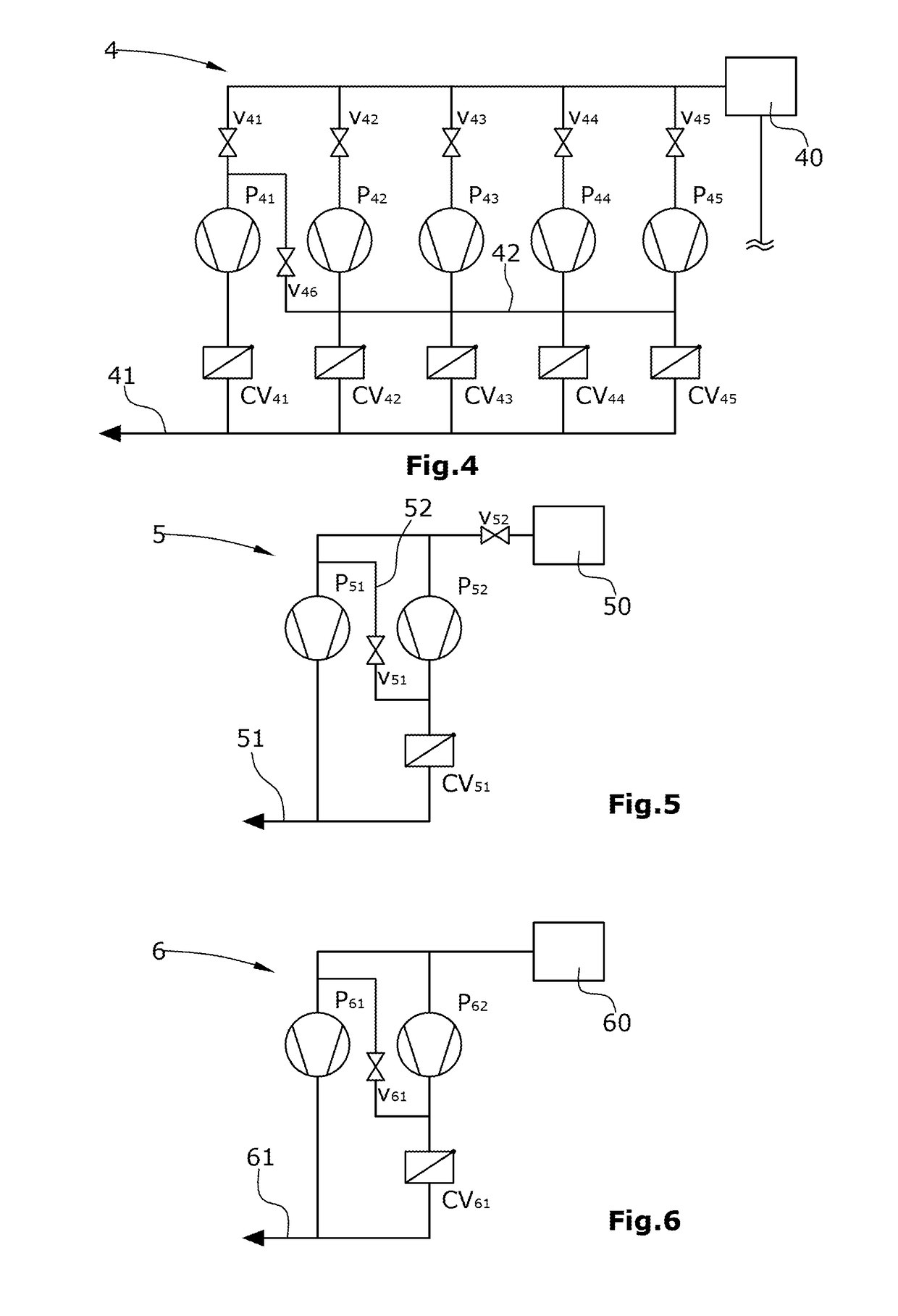
A vacuum pump system comprising a plurality of vacuum pumps which are connected to one another in parallel and are each connected on an inlet side to a chamber, having an outlet line which is connected on the outlet side of the vacuum pumps, and an intermediate line which connects the inlet side of at least one vacuum pump to the outlet line, wherein all the vacuum pumps are connected in parallel during a pumping-out period and at least one of the vacuum pumps is connected in parallel with the other vacuum pumps as a backing pump during an idle period.

Description

BACKGROUND1. Field of the Disclosure[0001]The present disclosure relates to a vacuum pump system for evacuating a chamber, in particular a process or lock chamber.2. Discussion of the Background Art[0002]Vacuum pump systems for regularly evacuating large chambers are known from prior art, FIG. 1. Frequently, vacuum pumps operating in a dryly compressing manner are used for this purpose. As a rule, these are combinations of backing pumps, such as screw pumps, claw pumps or multi-stage Roots pumps, and parallel-connected Roots pumps. In large pump systems a plurality of pumps and a plurality of Roots pumps are connected in parallel.[0003]Typically such pump systems are used in lock chambers, for example loadlock or unloadlock, e. g. in coating plants. In these plants a chamber must be pumped down from atmospheric pressure to a transfer pressure of typically approximately 0.1 mbar to 10 mbar within a short period of time, e. g. a pumping-down period of 20 seconds to 120 seconds. Subseq...

Claims


Application Information

Patent Timeline
IPC IPC(8): F04C28/06F04C25/02F04C28/02F04C28/26
CPCF04C28/065F04C25/02F04C28/02F04C28/06F04C28/26F04B37/14F04B41/06F04B49/06F04C23/001F04C2240/70
Inventor DREIFERT, THOMASMULLER, ROLANDPELIKAN, MAXSCHILLER, DIRKSCHNEIDENBACH, DANIELSTRATMANN, DIRK
Owner LEYBOLD HERAEUS GMBH & CO KG
Learn More