Frame Output Method And Device

a frame output and frame technology, applied in the field of display technologies, can solve the problems of compromising display quality, affecting the quality of image frames, so as to reduce the difficulty of assembly/disassembly, and enhance the display quality of image frames

Inactive Publication Date: 2018-04-19
SHENZHEN CHINA STAR OPTOELECTRONICS TECH CO LTD
View PDF2 Cites 0 Cited by
  • Summary
  • Abstract
  • Description
  • Claims
  • Application Information

AI Technical Summary

Benefits of technology

The present invention relates to a frame output device and method that improves image frame display quality by avoiding frame distortion caused by Over Driver (OD) calculation. The device achieves this by designing a separate middle frame with separate strips, which are slid into position along a back plate and reliably locked without requiring additional fastening means. The use of bolts or other fastening means is reduced, allowing for easier assembly and disassembly of the device. The invention also effectively thins the device by using a thin backlight module.

Problems solved by technology

Currently when a liquid crystal display (LCD) switches frames, a newly displayed frame cannot reach desired grey levels in time due to the limitation of liquid crystal response speed, therefore leading to streaks and compromising the display quality.
The memory for storage is sizable and costly, and the previous frame is often compressed before storage, and the compressed previous frame is decompressed before comparison.
There is a problem in the above described OD methods.
It is well known that compression usually leads to distortion.
Even when the previous frame (before compression) and the current frame are identical, distortion is inevitable in the output current frame after OD calculation.

Method used


Image

  • Frame Output Method And Device

Examples


Embodiment Construction

[0020]Embodiments of the present disclosure are described as follows with the accompanied drawings. However the embodiments are not intended to limit the scope, applicability or configuration of the disclosure in any way. Rather, the following description provides a convenient illustration for implementing exemplary embodiments of the disclosure. Various changes to the described embodiments may be made in the function and arrangement of the elements described without departing from the scope of the disclosure as set forth in the appended claims.

[0021]FIG. 1 is a functional block diagram showing a frame output device according to an embodiment of the present disclosure.

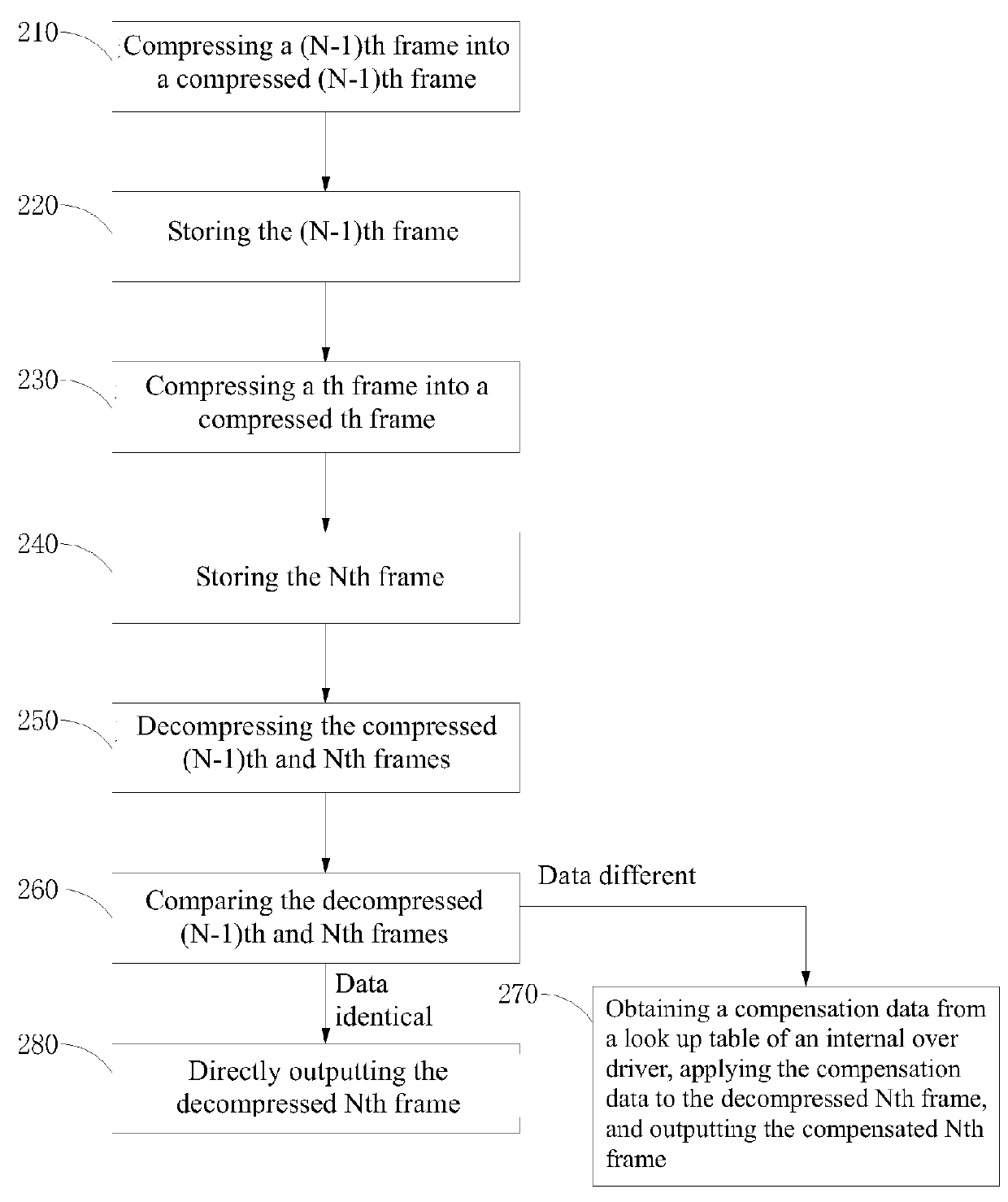
[0022]As illustrated, the frame output device includes a compression module 100, a storage module200, a decompression module 300, and a data comparison module 400.

[0023]The frame output device receives an (N−1)th frame and an Nth frame from a circuit of a previous stage. The (N−1)th frame is earlier than the Nth frame ...


PUM


Abstract

The present disclosure teaches a frame output method including the steps of: compressing a Nth frame into a compressed Nth frame using a compression method identical to that of compressing a (N−1)th frame into a compressed (N-1)th frame; storing the compressed Nth frame; decompressing the compressed Nth frame into a decompressed Nth frame using a decompression method identical to that of the decompressing the compressed (N−1)th frame into a decompressed (N−1)th frame; comparing the decompressed Nth frame and the decompressed (N−1)th frame and obtaining a comparison result; and providing an output frame according to the decompressed Nth frame and the comparison result. The present disclosure also teaches a frame output device. The frame output device and method described above are able to avoid the frame distortion problem resulted from Over Driver (OD) calculation, thereby enhancing image frame display quality.

Description

BACKGROUND OF THE INVENTION1. Field of the Invention[0001]The present invention relates to display technologies, and in particular to a frame output method and device.2. The Related Arts[0002]Currently when a liquid crystal display (LCD) switches frames, a newly displayed frame cannot reach desired grey levels in time due to the limitation of liquid crystal response speed, therefore leading to streaks and compromising the display quality. The LCD driver circuit as such usually employs an Over Driver (OD) method to twist liquid crystal molecules more rapidly so that a new frame may reach desired grey levels in time, the streaks are avoided, and frame dynamic display quality is enhanced.[0003]In existing OD methods, a previous frame is stored first and then a current frame is compared against the previous frame. The current frame is then output after OD calculation. The memory for storage is sizable and costly, and the previous frame is often compressed before storage, and the compres...

Claims


Application Information

Patent Timeline
Patent Type & Authority Applications(United States)
IPC IPC(8): H04N19/423H04N19/90H04N19/85H04N19/147H04N19/172G09G3/36
CPCH04N19/423H04N19/90H04N19/85H04N19/147H04N19/172G09G3/36G09G2340/02G09G2340/16G09G2360/16G09G2360/18
Inventor FU, WEIWU, YU
Owner SHENZHEN CHINA STAR OPTOELECTRONICS TECH CO LTD
Why Eureka
Try Eureka