Rain overflow basin for collecting and storing water

a technology for overflow basins and water, applied in separation devices, climate change adaptation, sedimentation settling tanks, etc., can solve problems such as increased maintenance and cleaning expenditure, easy malfunction, and complicated structure of screen devices

Active Publication Date: 2018-04-19
AMIBLU TECH AS
View PDF0 Cites 8 Cited by
  • Summary
  • Abstract
  • Description
  • Claims
  • Application Information

AI Technical Summary

Benefits of technology

The present invention provides a rain overflow basin with improved pollutant retention and reduced maintenance expenditure. A retention wall is provided to dam up water accumulating in the basin chamber, and a passage opening and storage space are provided between the retention wall and weir threshold. A purification device, in the form of a water-permeable movement-fixed retention element, is provided to purify the water draining from the basin chamber. The advantage is that the length and surface area of the retention element are not limited by the length of the retention wall and weir threshold, which reduces maintenance expenditure. The purification device can be easily retrofitted and is cost-effective. The orientation of the retention element does not change in the event of retrofitting, which simplifies the process.

Problems solved by technology

The screen device has a complicated structure, which is susceptible to malfunctions, in particular because of the rotational capability, the motorized drive, and the complicated design of the construction, for example, the arrangement of the baffle.
Thus, in particular in the case of elongated collecting basins and short discharge thresholds, problems can result with respect to an effective purification effect.
In addition, the rotation function of the screen drum causes an increased maintenance and cleaning expenditure, to ensure the rotating movement even in the case of a longer operating duration, for example, due to increased oiling or re-greasing in the rotating region.
Moreover, a motorized drive causes additional costs and maintenance work.
Furthermore, the stripping device has to be regularly cleaned and / or replaced.

Method used


Image

  • Rain overflow basin for collecting and storing water
  • Rain overflow basin for collecting and storing water
  • Rain overflow basin for collecting and storing water

Examples


first embodiment

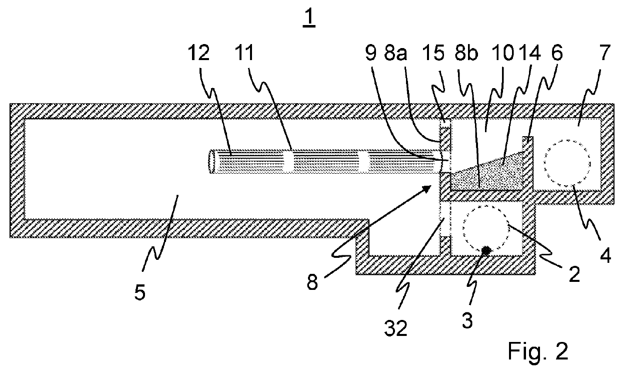
[0037]FIG. 2 shows a simplified sectional illustration of the rain overflow basin according to the invention having emergency spillway;

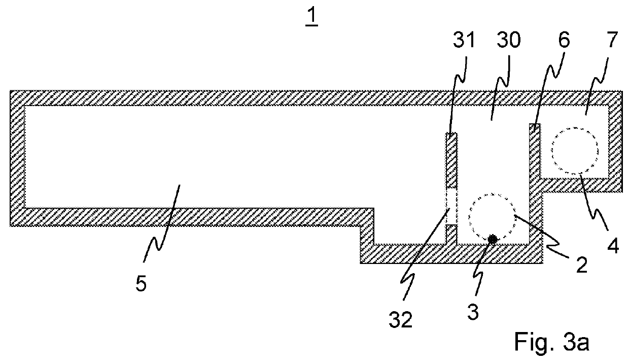
[0038]FIG. 3a shows a simplified sectional illustration of the rain overflow basin from FIG. 1 after completed first renovation step;

[0039]FIG. 3b shows a simplified sectional illustration of the rain overflow basin from FIG. 3a after completed further renovation measures;

[0040]FIG. 3c shows a simplified sectional illustration of the rain overflow basin from FIG. 3b after completed further renovation measures;

[0041]FIG. 3d shows a simplified sectional illustration of the rain overflow basin from FIG. 3c after completed further renovation measures;

[0042]FIG. 3e shows a simplified sectional illustration of the rain overflow basin from FIG. 3d after completed further renovation measures;

second embodiment

[0043]FIG. 3f shows a simplified sectional illustration of the rain overflow basin according to the invention;

[0044]FIG. 4 shows a simplified sectional illustration of a rain overflow basin without partition structure according to the prior art;

[0045]FIG. 5a shows a simplified sectional illustration of the rain overflow basin from FIG. 4 after completed first renovation step

[0046]FIG. 5b shows a simplified sectional illustration of the rain overflow basin from FIG. 6a after completed further renovation measures;

[0047]FIG. 5c shows a simplified sectional illustration of the rain overflow basin from FIG. 6b after completed further renovation measures;

third embodiment

[0048]FIG. 5d shows a simplified sectional illustration of the rain overflow basin according to the invention;

[0049]FIG. 6 shows a simplified perspective top view of the rain overflow basin from FIG. 3f;


PUM

PropertyMeasurementUnit
hole widthsaaaaaaaaaa
grain sizeaaaaaaaaaa

Abstract

A rain overflow basin for collecting and storing rainwater, mixed water, or wastewater, has an inflow, an outflow, a basin chamber, a basin spillway, which is equipped with a weir threshold and is connected downstream of the basin chamber. A drain discharges the basin spillway, and a purification device purifies water flowing from the basin chamber to the basin spillway. A retention wall between the basin chamber and the basin spillway dams up water accumulating in the basin chamber. Water draining from the basin chamber is dammed up in a storage space is between the retention wall and the weir threshold, to reach the basin spillway via the weir threshold. The retention wall includes a passage opening. A purification device extends into the basin chamber such that water draining from the basin chamber through the passage opening into the storage space flows through the retention element.

Description

[0001]This application claims benefit of Serial No. 16193741.2, filed 13 Oct. 2017 in Europen and which application is incorporated herein by reference. To the extent appropriate, a claim of priority is made to the above disclosed application.[0002]The present invention relates to a rain overflow basin for collecting and storing water and a method for the renovation of a rain overflow basin.TECHNOLOGICAL BACKGROUND[0003]Rain overflow basins are used in so-called mixed systems for drainage technology, for example, to achieve a buffer effect in the event of suddenly occurring precipitation events such as heavy rain. A drainage of large areas, for example, in the catchment area of cities or on freeways can thus occur. In mixed systems, in particular dirty water, external water, and rainwater is drained in mixed form (as so-called mixed water) in a common line.[0004]Rain overflow basins of the type in question can be embodied as catch basins, pass-through basins, or composite basins. Ca...

Claims


Application Information

Patent Timeline
Patent Type & Authority Applications(United States)
IPC IPC(8): E03F5/10E03F5/12
CPCE03F5/105E03F5/125E03F5/101B01D21/0012B01D21/2444B01D2221/12Y02A10/30E03F5/14
Inventor NAPIERSKI, UWESTARATZKE, HEINZ JURGENWENDT, MANUELA
Owner AMIBLU TECH AS
Why Eureka
Try Eureka