Electric damper for vehicle

Active Publication Date: 2018-04-19
HYUNDAI MOBIS CO LTD
View PDF0 Cites 3 Cited by
  • Summary
  • Abstract
  • Description
  • Claims
  • Application Information

AI Technical Summary

Benefits of technology

The present invention is an electric damper for a vehicle that reduces power consumption by using shocks from the outside of the vehicle to move a gear bar and rotate a rotator, which generates electricity. This results in a reduction of power consumption. Additionally, the invention includes a stator, rotator, and gear bar for each wheel of the vehicle. This allows for better control of the damping operations of the wheels based on the vehicle's operating conditions, providing more stable driving conditions.

Problems solved by technology

Generally, in a vehicle that is moving, vibrations are generated by unevenness of road surfaces or the operation of an engine.
A configuration of a damper provided with a motor to control the operation of the damper was proposed, but there is a problem in that it cannot generate electricity using energy transmitted from the outside of a vehicle to the damper.

Method used


Image

  • Electric damper for vehicle
  • Electric damper for vehicle
  • Electric damper for vehicle

Examples


Embodiment Construction

[0025]Hereinafter, an electric damper for a vehicle in accordance with an embodiment of the present invention will be described in detail with reference to the accompanying drawings. The size of each element, the thickness of lines indicating the element, etc. may be exaggerated for the purpose of clarity and convenience of description.

[0026]The terms and words used for elements in the description of the present invention are determined based on the functions of the elements in the present invention. The terms and words may be changed depending on the intention or custom of users or operators, so that they must be defined based on the whole content of the present specification.

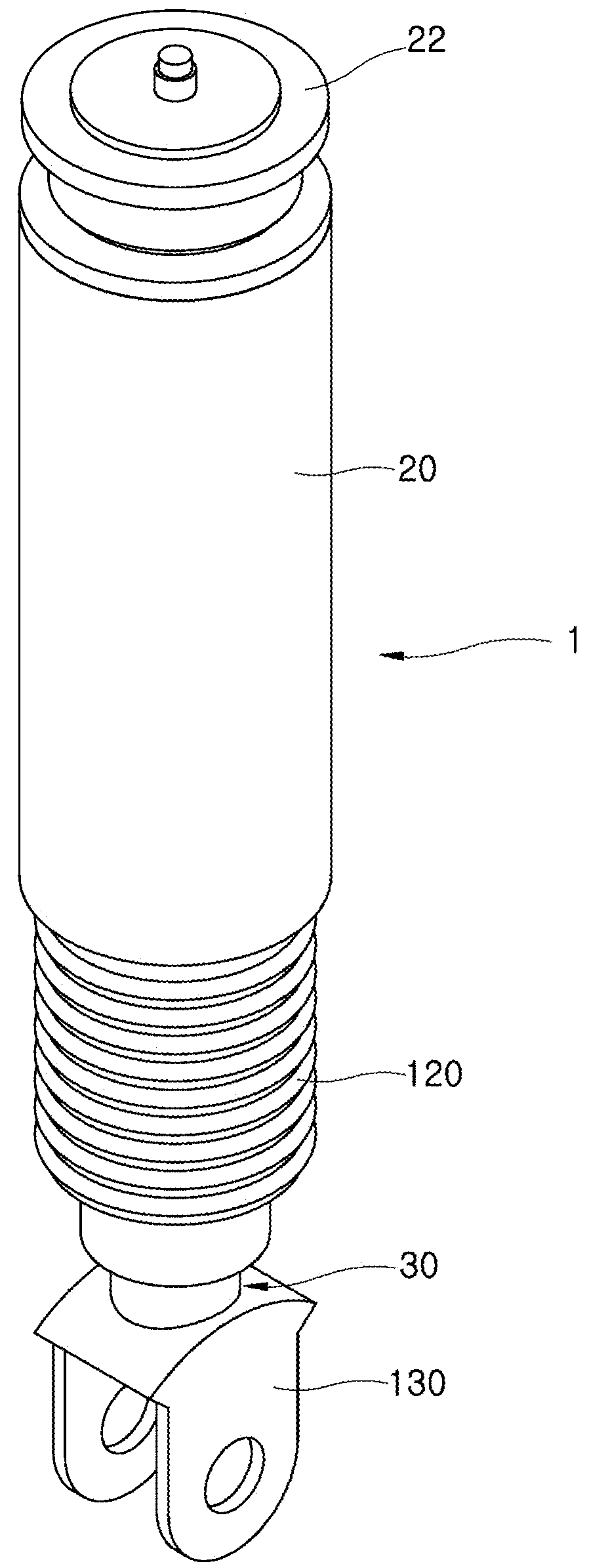
[0027]FIG. 1 is a perspective view schematically illustrating the installation of en electric damper for a vehicle in accordance with an embodiment of the present invention. FIG. 2 is a perspective diagram illustrating the electric damper in accordance with an embodiment of the present invention. FIG. 3 is a d...


PUM


Abstract

An electric damper for a vehicle may include: a housing body fixed to a vehicle body; a gear bar including a first end coupled to a knuckle of a wheel, and a second end extending into the housing body, with a rack gear provided on the gear bar; a first intersection gear unit installed in a direction intersecting a movement direction of the gear and configured to engage with the rack gear and rotate; a first power transmitting gear unit configured to engage with the first intersection gear unit and rotate, and including a rotating shaft installed parallel to the gear bar; a rotator configured to engage with the first power transmitting gear unit, and provided in a shape enclosing an outer surface of the gear bar; and a stator installed in the housing body at a position facing the rotator and having a magnetic force.

Description

CROSS-REFERENCES TO RELATED APPLICATIONS[0001]The present application claims priority to Korean application number 10-2016-0134912, filed on Oct. 18, 2016, which is incorporated by reference in its entirety.BACKGROUND OF THE INVENTION[0002]The present invention relates to an electric damper for a vehicle, and more particularly, to an electric damper for a vehicle which is capable of generating electricity using energy transmitted to the damper and controlling a damping operation of a wheel depending on operating conditions of the vehicle.[0003]Generally, in a vehicle that is moving, vibrations are generated by unevenness of road surfaces or the operation of an engine. To restrain such vibrations, dampers are installed in the vehicle.[0004]The dampers are installed on axles to dampen vibrations transmitted from road surfaces when the vehicle moves. A configuration of a damper provided with a motor to control the operation of the damper was proposed, but there is a problem in that it ...

Claims


Application Information

Patent Timeline
IPC IPC(8): B60G17/015F16F15/02
CPCB60G17/0157F16F15/022B60G2500/104B60G2202/25F16F2232/04B60G2202/42B60G17/06B60G2204/419F16F15/03F16F2232/06B60G13/14F16H19/04F16H1/14B60G2204/4192B60G2800/954
Inventor PARK, KYUNG RYUL
Owner HYUNDAI MOBIS CO LTD
Why Eureka
Try Eureka