Composite polymer electrolyte membrane for fuel cell, and method of manufacturing the same
uel cell technology, applied in fuel cells, sustainable manufacturing/processing, climate sustainability, etc., can solve the problems of gas barrier characteristics of the polymer electrolyte membrane that are significantly deteriorated, ionic conductivity, mechanical strength, and difficulty in implementing a polymer electrolyte membrane having high durability, etc., to achieve excellent durability and performance, high membrane density, and uniform composition
Active Publication Date: 2018-04-12
KOREA INST OF SCI & TECH
View PDF0 Cites 0 Cited by
- Summary
- Abstract
- Description
- Claims
- Application Information
AI Technical Summary
Benefits of technology
[0021]A composite polymer electrolyte membrane according to the present disclosure may exhibit excellent durability and performance as compared to the thickness by having a uniform composition and a high membrane density without any void therein. Specifically, the composite polymer electrolyte membrane may have a hydrogen ion exchange characteristic, mechanical strength, and dimensional stability, which are equal to or better than those of an existing polymer electrolyte membrane for a fuel cell, and may have a gas permeability, which is more improved than that of the existing polymer electrolyte membrane for a fuel cell.
[0022]Further, the composite polymer electrolyte membrane is manufactured by an a
Problems solved by technology
However, since an increase in thickness of a polymer electrolyte membrane for implementing high mechanical strength also increases the resistance of the corresponding membrane, an increase in resistance may result in low ionic conductivity of the corresponding membrane.
That is, it may be considerably difficult to implement a polymer electrolyte membrane having high durability while making the membrane thin, such that the membrane has high ionic conductivity.
Further, a considerable amount of water may be absorbed within a hydrophilic domain of the corresponding polymer electrolyte membrane when a fuel cell is driven, so that the ionic cond
Method used
View moreImage
Smart ImageViewing Examples
Examples
 PUM
 Abstract
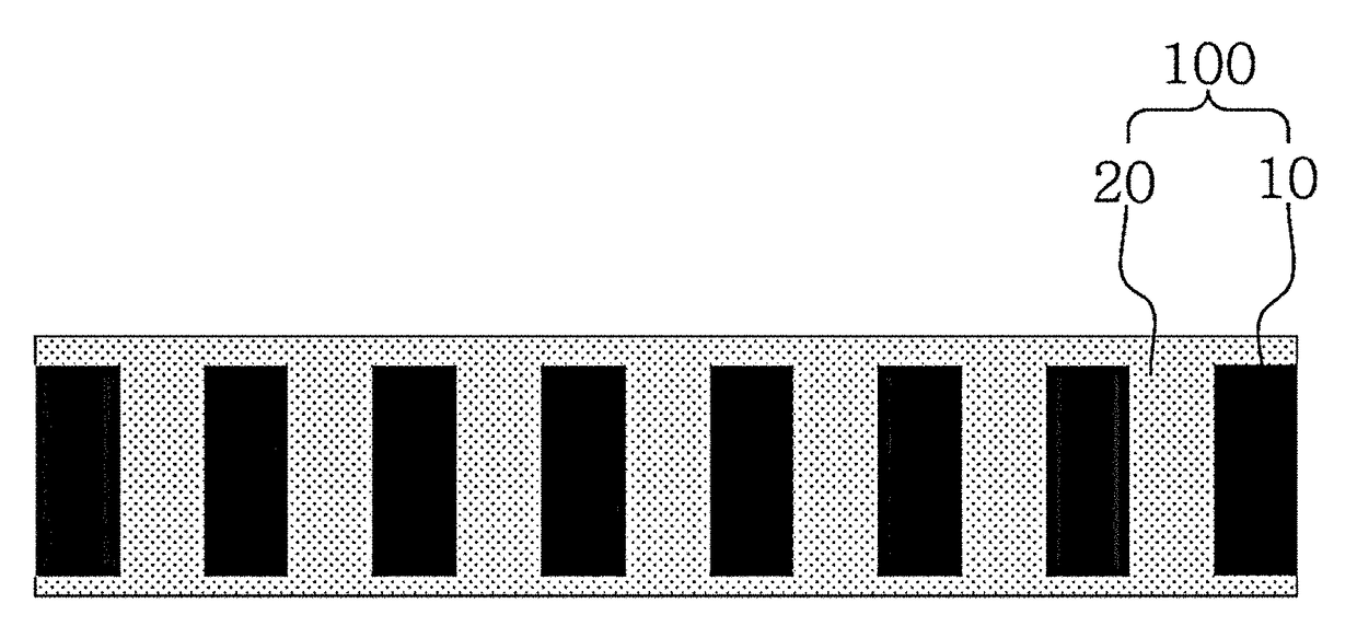
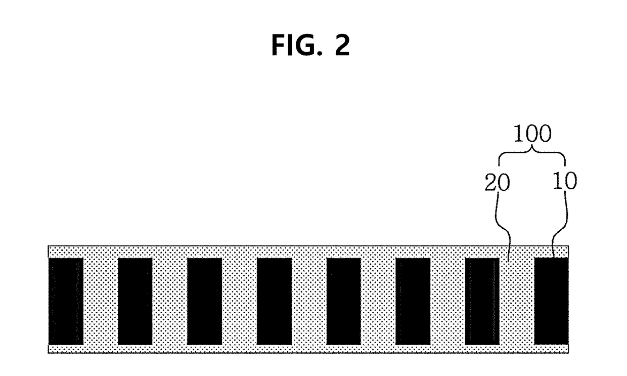
Provided is a composite polymer electrolyte membrane for a fuel cell, including: a porous fluorinated polymer support; and a perfluorinated sulfonic acid polymer resin membrane which fills the inside of pores of the porous perfluorinated polymer support and covers an external surface of the porous fluorinated polymer support.
Description
CROSS-REFERENCE TO RELATED APPLICATION[0001]This application claims the priority of Korean Patent Application No. 10-2016-0132215, filed on Oct. 12, 2016, and all the benefits accruing therefrom under 35 U.S.C. § 119, the contents of which in its entirety are herein incorporated by reference.BACKGROUND1. Field[0002]The present disclosure relates to a composite polymer electrolyte membrane for a fuel cell, and a method of manufacturing the same. More specifically, the present disclosure relates to a composite polymer electrolyte membrane for a polymer electrolyte membrane fuel cell (PEMFC), and a method of manufacturing the same.[0003][Description of the National Support Research and Development][0004]This study was conducted with the support from the Ministry of Trade, Industry and Energy, Republic of Korea under the supervision of the Korea Institute of Energy Technology Evaluation and Planning, the project title is the Development of New and Renewable Energy Core Technology, and t...
Claims
Login to View More Application Information
Patent Timeline
 IPC IPC(8): H01M8/106H01M8/1039H01M8/1069
CPCH01M8/106H01M8/1039H01M8/1069H01M2008/1095H01M8/1053Y02E60/50Y02P70/50
Inventor KIM, JIN YOUNGJO, SUNHEELEE, SO YOUNGYOO, SUNG JONGJANG, JONG HYUNKIM, HYOUNG-JUHNHAN, JONGHEENAM, SUK WOOLIM, TAE HOON
Owner KOREA INST OF SCI & TECH
Features
- R&D
- Intellectual Property
- Life Sciences
- Materials
- Tech Scout
- Unparalleled Data Quality
- Higher Quality Content
- 60% Fewer Hallucinations
Learn More Browse by: Latest US Patents, China's latest patents, Technical Efficacy Thesaurus, Application Domain, Technology Topic, Popular Technical Reports.
© 2025 PatSnap. All rights reserved.Legal|Privacy policy|Modern Slavery Act Transparency Statement|Sitemap|About US| Contact US: help@patsnap.com


