
Backlight modules and liquid crystal devices

a backlight module and liquid crystal technology, applied in the field of backlight modules and liquid crystal devices, can solve the problems of optical leakage, difficult control of optical paths, easy damage of chips, etc., and achieve the effect of reducing costs

Active Publication Date: 2018-04-12
SHENZHEN CHINA STAR OPTOELECTRONICS TECH CO LTD
View PDF0 Cites 2 Cited by
  • Summary
  • Abstract
  • Description
  • Claims
  • Application Information

AI Technical Summary

Benefits of technology

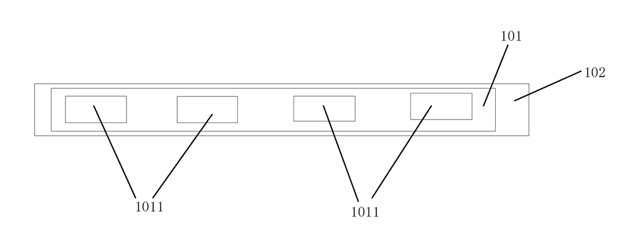
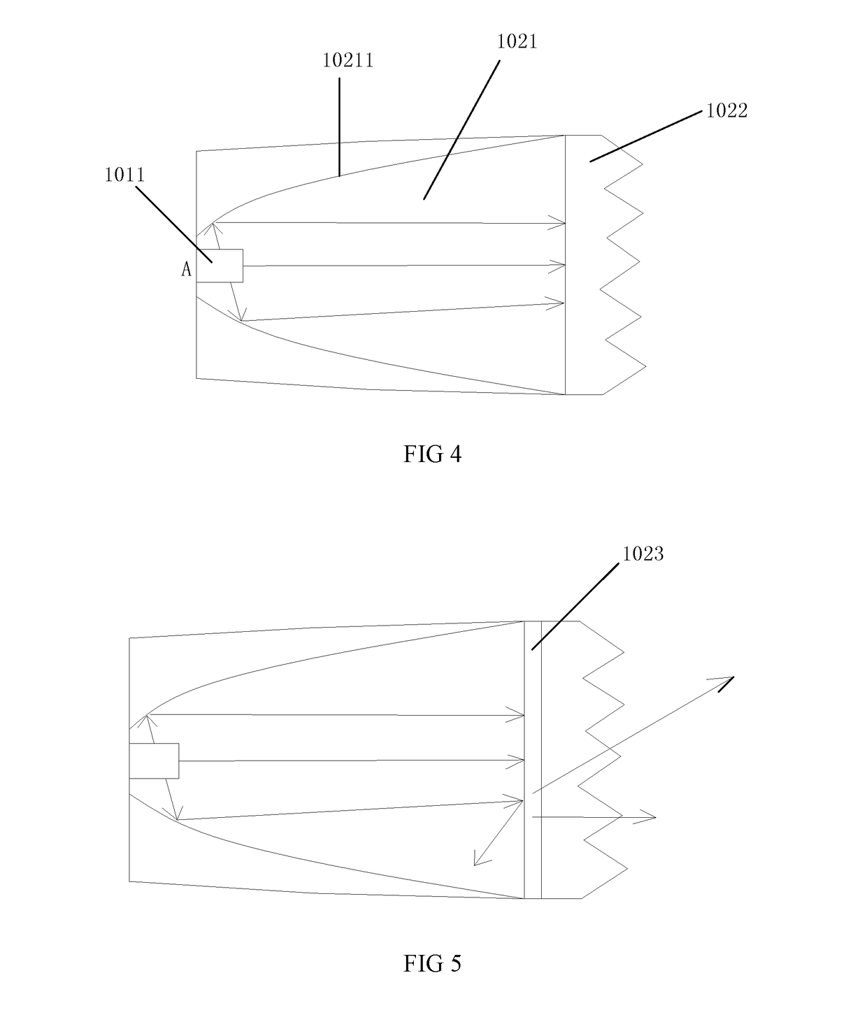
The present invention relates to a backlight module and a LCD that can improve the optical utilization of the CSP (chip-scale package) when incorporated into an edge-type BLU (backlight unit). The invention also addresses the issue of optical leakage. The backlight module includes a LED light source and a lens bar. The LED light source has multiple LED lamps encapsulated by CSP, which is a cost-effective solution. The lens bar has curved surfaces that help to aggregate the light beams emitted from the LED lamps. This design allows for a thinner and lighter backlight module. The invention also allows for the incorporation of the LED light source into an edge-type BLU, resulting in a thin and light design.

Problems solved by technology

However, there are several issue with respect to the CSP.
First, there is no support within the package, and thus the chip may be easily damaged.
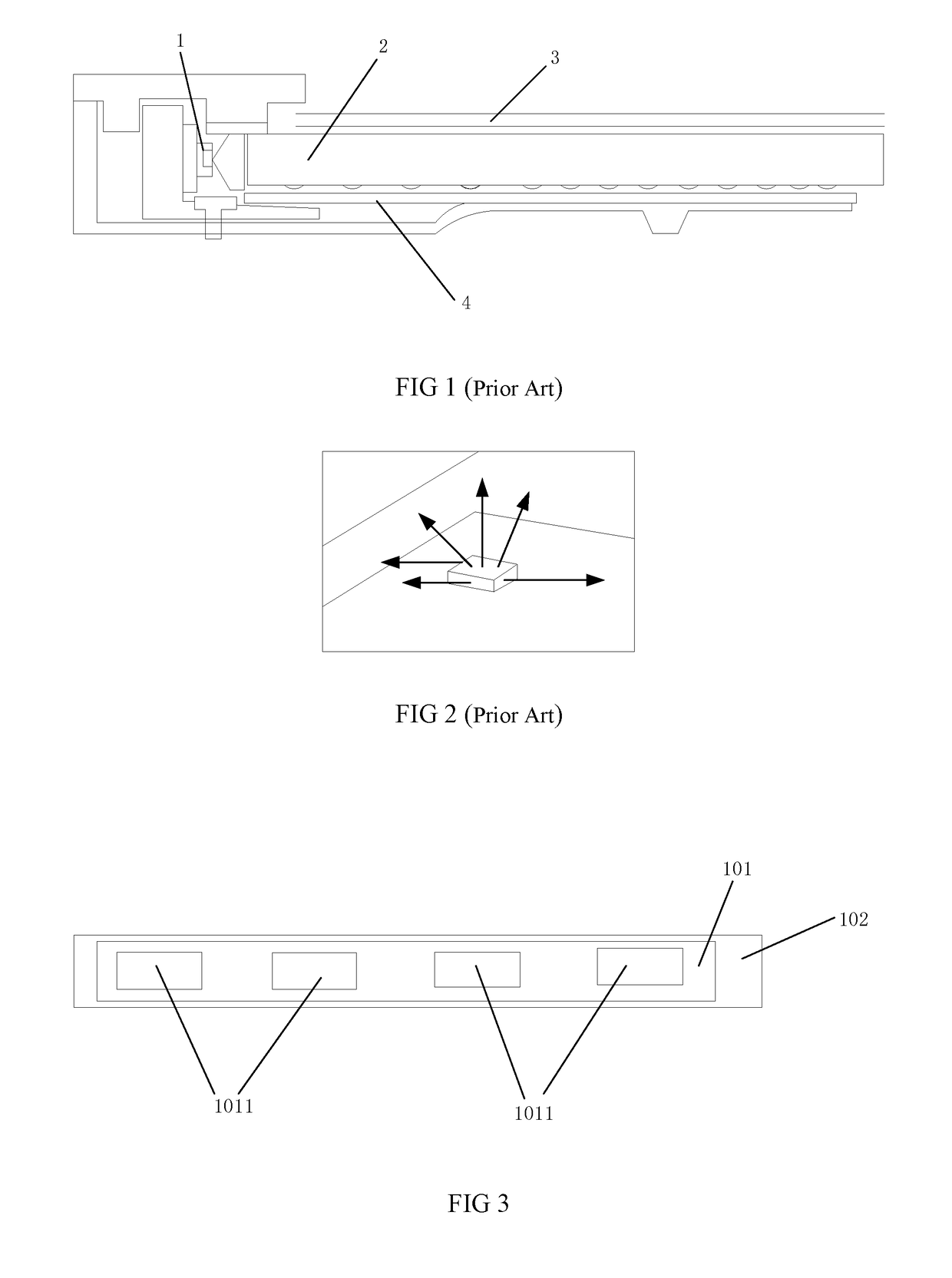
Second, the package may emit the light beams from five surfaces, and thus it is difficult to control the optical path, which results in optical leakage.
In view of the above, though cost of the CSP is low, the CSP is not applicable for the edge-type BLU.
In addition, when the number of the light sources is reduced, the hotspot issue may occur at the light incident side, which affects the display performance.

Method used


Image

  • Backlight modules and liquid crystal devices
  • Backlight modules and liquid crystal devices
  • Backlight modules and liquid crystal devices

Examples


Embodiment Construction

[0030]Embodiments of the invention will now be described more fully hereinafter with reference to the accompanying drawings, in which embodiments of the invention are shown.

[0031]Currently, the backlit adopted by LCDs is LED, and the structure is shown in FIG. 1.

[0032]The BLU includes a light source 1, a light guiding plate 2, at least one optical film 3, and a reflective sheet 4. The light source 1 may be LED. The light guiding plate 2 is configured for transmitting the light beams to convert the dot light source into a surface light source. The optical film 3 is arranged above a top surface of the light guiding plate 2. The reflective sheet 4 is arranged below the light guiding plate 2.

[0033]With respect to the direct-lit BLU, chip scale package (CSP) has been widely adopted. The CSP adopts flip chip solution, which may greatly increase the driving voltage of LED so as to enhance the lightness value of the LED. Incorporating with other solutions, the number of the LEDs may be redu...


PUM


Abstract

The present disclosure relates to a backlight module and a liquid crystal device. The backlight module includes a LED light source and a lens bar. The LED light source is arranged on the LED substrate and includes a plurality of LED lamps encapsulated by CSP. The lens bar is arranged in the front of the LED light source and includes a plurality of chambers. Internal walls of the chambers are parabola-shaped curved surfaces. Each of the LED lamps is arranged in a rim of a focal point formed by the parabola-shaped curved surface such that the curved surface above the LED lamps is symmetrical to that below the LED lamps. With such configuration, the LED light source encapsulated by the CSP may be incorporated in edge-type BLU so as to avoid the optical leakage issue.

Description

BACKGROUND OF THE INVENTION1. FIELD OF THE INVENTION[0001]The present disclosure relates to liquid crystal display technology, and more particularly to a backlight module and a liquid crystal device (LCD).2. DISCUSSION OF THE RELATED ART[0002]Currently, backlit of LCDs generally adopt light emitting diode (LED) as a light source. The back light unit (BLU) of edge-type may include: a light, such as LED, a light guiding plate for transmitting light beams to provide a surface light source, optical films above the light guiding plate, and a reflective sheet below a bottom of the light guiding plate.[0003]Currently, with the technology development, the optical components, such as the light source, have been updated continuously. With respect to the direct-lit BLU, chip scale package (CSP) has been widely adopted. The CSP adopts flip chip solution, which may greatly increase the driving voltage of LED so as to enhance the lightness value of the LED. Incorporating with other solutions, the...

Claims


Application Information

Patent Timeline
IPC IPC(8): G02F1/1335
CPCG02F1/133603G02F1/133606G02F1/133615F21V5/04F21W2107/10G02B6/003G02B6/0031G02B6/0065G02B6/0073
Inventor CHANG, JIANYU
Owner SHENZHEN CHINA STAR OPTOELECTRONICS TECH CO LTD
Learn More