
Vehicle control device

a technology for controlling devices and vehicles, applied in vehicle position/course/altitude control, process and machine control, instruments, etc., can solve problems such as the inability to say that the traveling efficiency is good, and the possibility of the host vehicle unnecessarily meandering, etc., to achieve superior traveling efficiency and comfort.

Active Publication Date: 2018-04-12
HONDA MOTOR CO LTD
View PDF7 Cites 42 Cited by
  • Summary
  • Abstract
  • Description
  • Claims
  • Application Information

AI Technical Summary

Benefits of technology

The present invention is a vehicle control device that allows a car to drive automatically or with assistance. It uses information from sensors to calculate the ideal route for driving based on efficiency and comfort. The device calculates a route that minimizes curve radius, travel distance, and the difference between the vehicle's travel range and the center line. This results in a more efficient and comfortable drive, reducing the need for excessive steering or braking. By following this ideal route, the device ensures the car travels smoothly and comfortably during both automatic driving and assisted driving.

Problems solved by technology

However, it cannot be said that the traveling efficiency is good, simply by controlling traveling of the vehicle so as to follow along the center line that is calculated on the basis of detection information from the external environment sensors.
For example, the shape of the travel path to be recognized is easily changed due to the presence of noise when detecting left and right boundary lines of the travel path, and without a guarantee of time-sequential continuity, there is a possibility for the host vehicle to meander unnecessarily.

Method used


Image

  • Vehicle control device
  • Vehicle control device
  • Vehicle control device

Examples


Embodiment Construction

[0057]A preferred embodiment of a vehicle control device according to the present invention will be presented and described in detail below with reference to the accompanying drawings.

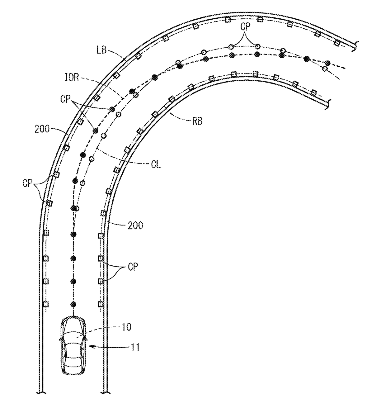
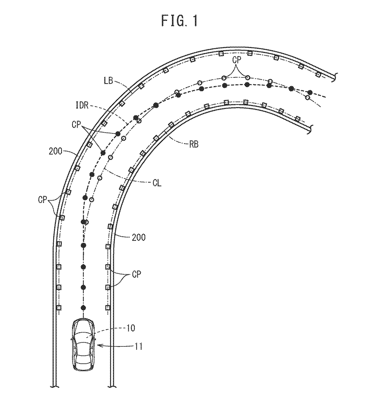
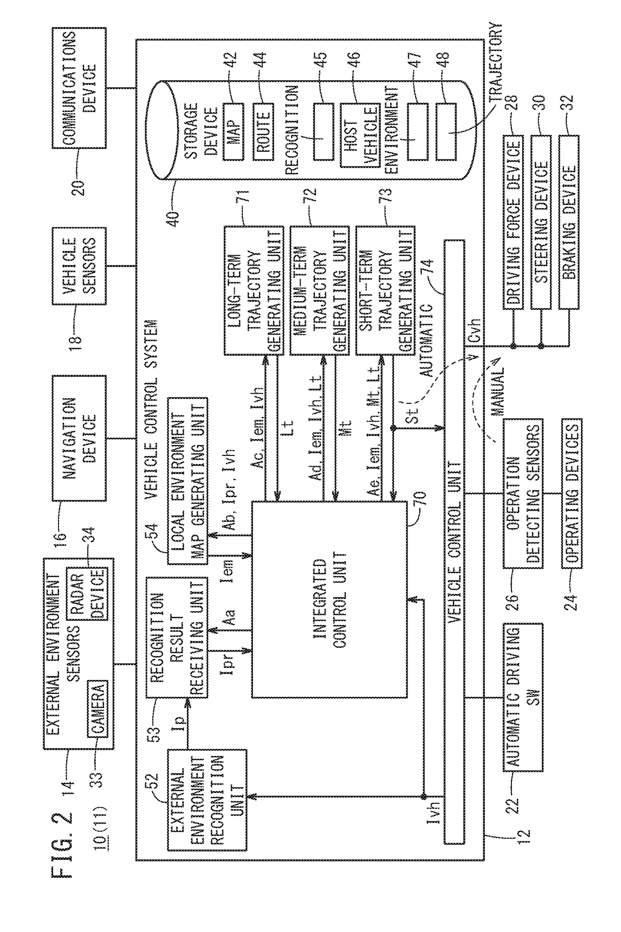
[0058]As shown in FIG. 1, the vehicle control device 10 according to one embodiment of the present invention is installed in a vehicle 11 (hereinafter also referred to as a host vehicle 11) and controls automatic driving of the host vehicle 11. In such automatic driving, a speed control (acceleration, deceleration, speed maintenance, etc.) for adjusting the vehicle velocity of the host vehicle 11, and a steering angle control for adjusting the direction of travel of the host vehicle 11 are performed in an integral manner. Further, at this time, the vehicle control device 10 recognizes the surrounding environment of the host vehicle 11 including a travel path, and causes the host vehicle 11 to travel along an appropriate route on the travel path.

[0059]In particular, the vehicle control device 10 is conf...


PUM


Abstract

A vehicle control device is installed in a host vehicle and is configured to be capable of performing automatic driving or providing a driving support. The vehicle control device includes a left / right boundary line generating unit that calculates left and right boundary lines of a travel path on which the host vehicle travels. Further, the vehicle control device includes an ideal travel route generating unit that sets constraint points through which the host vehicle passes within a range of the left and right boundary lines, and furthermore, calculates an ideal travel route in which a curvature with the constraint points serving as a constraint condition, a travel distance, and a difference from a center line are minimized.

Description

CROSS-REFERENCE TO RELATED APPLICATION[0001]This application is based upon and claims the benefit of priority from Japanese Patent Application No. 2016-201246 filed on Oct. 12, 2016, the contents of which are incorporated herein by reference.BACKGROUND OF THE INVENTIONField of the Invention[0002]The present invention relates to a vehicle control device which performs automatic driving or provides a driving assist for a vehicle.Description of the Related Art[0003]In a vehicle control device that performs automatic driving or provides a driving assist for a vehicle (a user's own vehicle, also referred to herein as a “host vehicle”), the surrounding environment of the host vehicle is detected by peripheral recognition sensors (external environment sensors) such as cameras or the like, and on the basis of the information detected thereby, a travel path on which the host vehicle travels is recognized (see Japanese Laid-Open Patent Publication No. 2016-112911). For example, the vehicle co...

Claims


Application Information

Patent Timeline
IPC IPC(8): B60W30/12B60W10/20B60W40/072G06K9/00G05D1/02G08G1/16
CPCB60W30/12B60W10/20B60W40/072G06K9/00798G05D1/0212G08G1/167G05D2201/0213B60W40/02G08G1/0112G08G1/096775G08G1/096783G08G1/096791G08G1/165G08G1/166B62D15/025B60W2050/0052B60W30/18145B60W30/0956B60W30/025B60W30/045G06V20/588
Inventor ABE, CHIHIROKATO, DAICHISUMIOKA, TADASHITAKAHASHI, KAZUYUKI
Owner HONDA MOTOR CO LTD
Learn More