Water Collection/Deflection Arrangements

Active Publication Date: 2018-04-05
BALTIMORE AIRCOIL CO INC
View PDF0 Cites 10 Cited by
  • Summary
  • Abstract
  • Description
  • Claims
  • Application Information

AI Technical Summary

Benefits of technology

This patent is about improving evaporative cooling equipment by reducing airflow resistance and increasing air capacity. The invention achieves this by overlapping gutters and sloped panels to manage spray water flow and improve air distribution. The systems are designed to minimize airside pressure drop, catch water droplets, and create an extended rain zone for additional cooling. The invention also includes the use of overlapping gutter water collection systems and louvers to isolate the sump area from the fan area and improve water catching performance. Overall, the invention improves the efficiency and performance of evaporative cooling equipment.

Problems solved by technology

Given the near perpendicular arrangement of the entering air velocity provided by the fan, the turning losses to the heat exchanger significantly contribute to the total static pressure acting against the fan and increased fan energy consumption for a given airflow.
For forced draft evaporative cooling equipment using an unhoused fan, the fans and fan plenum are separated from the heat exchanger for water management concerns, and are not positioned directly under the heat exchanger section, resulting in poor fan performance due to higher airflow resistance, large unit footprint and higher unit cost due to the side-by-side heat exchanger and fan sections.
However, some designs require the complete footprint of the unit to be covered by the overlapping gutter water collection systems.
Finally, keeping the spray water as far away from the air intake as possible greatly reduces to risk of water splashing out through the fan, and the risk of freezing in the winter, especially when the fans are not in operation.

Method used


Image

  • Water Collection/Deflection Arrangements
  • Water Collection/Deflection Arrangements
  • Water Collection/Deflection Arrangements

Examples


Embodiment Construction

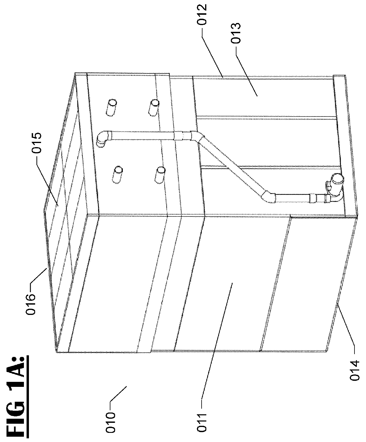
[0030]Referring now to the Figures and particularly FIG. 1A, an evaporative indirect heat exchanger product apparatus generally designated by 010 is shown. The apparatus has four vertical sides that include a connection end 013, an opposite to connection end 016, an air inlet end 012, and an opposite to air inlet end 011. The apparatus also has a bottom end 014 and a top air discharge end 016.

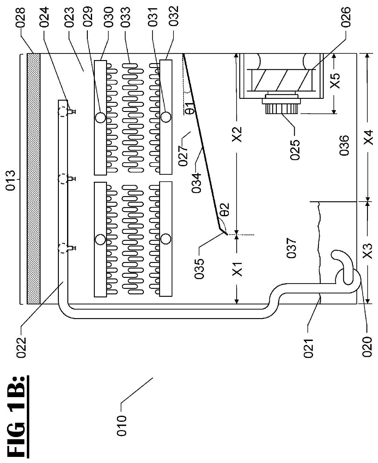
[0031]Now referring to FIG. 1B, the main internal and external components are better identified from a side sectional view of connection end 013. Hot process fluid may enter indirect heat exchanger 023 from top inlet connection(s) 029 to be distributed through top heat exchanger header 030 through serpentine tube circuits 033 to be collected by bottom header exchanger header 032 to leave cooled process fluid exiting through bottom outlet connection(s) 031. Process fluid is indirectly cooled from air forced through heat exchanger by fan 026 and cooled water collected from sump 021 by pump 020 to...


PUM


Abstract

Improved water management systems which deflect or collect evaporative liquid exiting counterflow heat exchangers and improve airflow distribution are provided. Such heat exchangers include open cooling towers, closed circuit cooling towers, and evaporative condensers. The improved water management systems eliminate water splash out and the noise associated with water splashing. Further, when the fan assemblies are located below the evaporative heat exchanger, the improved water management systems keep the fans dry and prevent freezing in subzero climates.

Description

RELATED APPLICATIONS[0001]The application claims benefit of U.S. provisional application 62 / 402,038, filed Sep. 30, 2016, the entirety of which is hereby incorporated herein by reference.BACKGROUND AND SUMMARY OF THE INVENTION[0002]This invention concerns evaporative cooling towers, fluid coolers and evaporative condensers, and specifically the amelioration of the air and spray water flow within the evaporative cooling equipment. This invention improves air distribution while reducing airflow resistance to increase the thermal capacity for a given footprint of the evaporative cooling tower. In addition, this invention seeks to provide self-cleaning, easy to access, inspect and maintain evaporative cooling equipment.[0003]The improvement in airflow distribution, and decrease in airflow resistance, is achieved by reducing the amount of obstruction and turns in the airflow path, and by opening the plenum area around the fan. Typical forced draft evaporative cooling equipment with side ...

Claims


Application Information

Patent Timeline
IPC IPC(8): F28F25/12F28F25/04
CPCF28F25/12F28F25/04F28C1/00F28C1/14F28D5/02Y02B30/70
Inventor ROUSSELET, YOHANN LILIANAUTH, CHRISTOPHER PATRICKMALAMUD, DINA
Owner BALTIMORE AIRCOIL CO INC
Why Eureka
Try Eureka