
Image capturing apparatus, system and method

a technology of image capture and image, applied in the field of image capture apparatus, system and method, can solve the problems of high power consumption mode, inability to determine whether the image captured is actually an image of a real object, and the use of cameras as sensors

Active Publication Date: 2018-03-29
STMICROELECTRONICS (RES & DEV) LTD +1
View PDF6 Cites 44 Cited by
  • Summary
  • Abstract
  • Description
  • Claims
  • Application Information

AI Technical Summary

Benefits of technology

The patent describes an apparatus that uses a time of flight (ToF) single-photon avalanche diode (SPAD) based range detecting module to determine the distance between an object and the apparatus. This information is used to control a camera to capture images of the object. The apparatus can also use multiple cameras with overlapping fields of view to capture images of the object. The system can also verify the identity of the object based on the distance determination and control security functions based on the verification. The technical effect of this patent is to provide a more accurate and efficient method for detecting and identifying objects within a field of view of a camera.

Problems solved by technology

Such uses of cameras as sensors however has several issues.
Firstly the camera is typically operated in an always on mode which is a high power consumption mode.
Secondly a single camera may be unable to determine whether the image captured is actually an image of a real object or an image of an image of the object.
Thirdly capturing of images for security purposes can produce poor results where there is any transparent surface between the camera and the object being imaged.
For example when a person is located behind a pane of glass the camera on the other side may not be able to capture an in-focus image to identify the person.
Errors in the 3D models can for example lead to incorrect results.
Furthermore limitations in cameras, algorithms and device production prevent effective correction of all errors, motions and variations.
These issues are typically worse in mobile devices because of the limited computation power, battery capacity and movement of the device during capture.

Method used


Image

  • Image capturing apparatus, system and method
  • Image capturing apparatus, system and method
  • Image capturing apparatus, system and method

Examples


Embodiment Construction

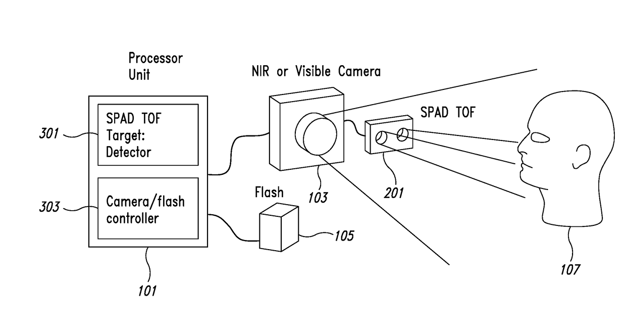
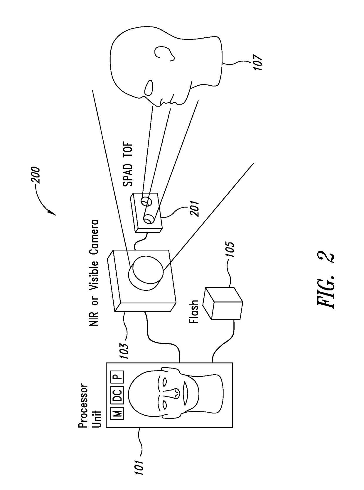
[0051]In an embodiment, a single-photon avalanche diode (SPAD) time-of-flight (ToF) sensor is employed to assist a processor unit or circuit in sensor applications employing cameras. This assistance may, for example, be at least one of: an auxiliary presence detector; an auxiliary multi-zone presence detector; an auxiliary multi-range presence detector; an auxiliary focus distance detector; and an object shape verifier.

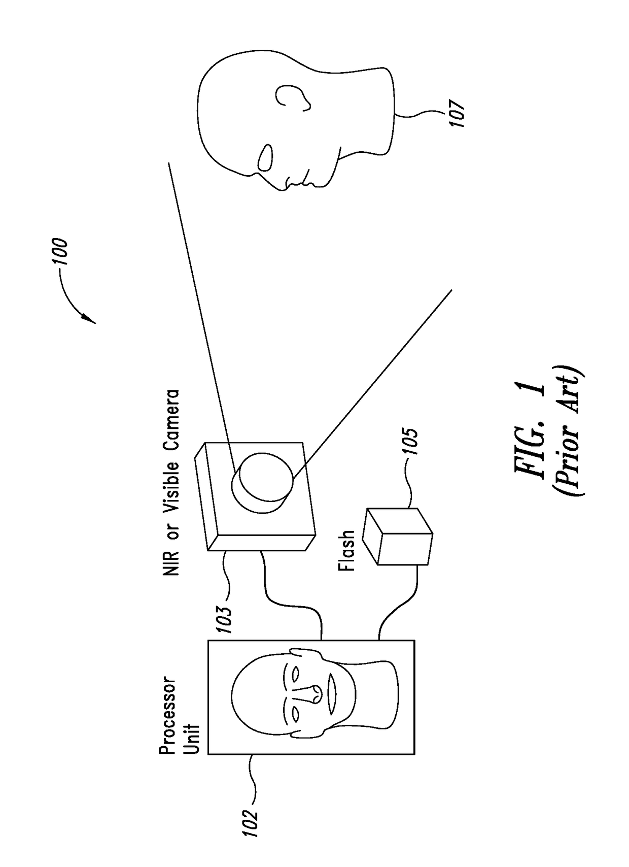
[0052]In order to aid understanding of the embodiments described herein we first describe a typical camera security system. FIG. 1 shows a camera employed as part of a security implementation system. The system 100 comprises a near infrared, infrared, or visible camera 103 which is configured to capture an image of an object 107, for example a person shown in FIG. 1 as the ‘head’, and output the image to a processor unit or circuitry 102. Furthermore the system may comprise a flash 105 or illumination source which is coupled to the processor unit 102 and furthermore i...


PUM


Abstract

An apparatus includes time of flight single-photon avalanche diode (ToF SPAD) circuitry. The ToF SPAD circuitry generates indications of distance between the apparatus and an object within a field of view. A processor receives the indications of distance and controls at least one image sensor, such as a camera, to capture at least one image based on at least one indication of distance. The processor determines whether an image is a true representation of an expected object by comparing multiple indications of distance associated with the object to an expected object distance profile and comparing the image to at least one expected object image.

Description

BACKGROUNDTechnical Field[0001]This disclosure relates to an apparatus and in particular but not exclusively to an apparatus with an array of photosensitive devices.Description of the Related Art[0002]The use of cameras as networked sensors or networked devices is known. Cameras for example may be used as sensors within many applications. For example a camera or cameras may be used in sensors implemented within the internet of things (IOT) to monitor activity for controlling household devices, in industrial processes for verification of objects and in security for biometric authentication.[0003]A specific example may be the use of a camera (or multiple cameras) employed as a security sensor for capturing images. The security sensor may be used to control access to an area based on whether the image biometrically identifies the person in front of the camera.[0004]Such uses of cameras as sensors however has several issues. Firstly the camera is typically operated in an always on mode ...

Claims


Application Information

Patent Timeline
Patent Type & Authority Applications(United States)
IPC IPC(8): G06T7/55G06T7/521G06T7/73H04N5/235
CPCG06T7/55G06T7/521G06T2207/10028H04N5/2354G06T7/74G01S7/48G01S7/4802G01S7/497G07C9/37G01S17/04G01S17/86G01S17/894G06V40/166H04N23/74
Inventor YANG, XIAOYONGDUTTON, NEALE
Owner STMICROELECTRONICS (RES & DEV) LTD
Learn More