A fluidic dispensing device and stir bar feedback method and use thereof

Active Publication Date: 2018-03-29
FUNAI ELECTRIC CO LTD
View PDF2 Cites 0 Cited by
  • Summary
  • Abstract
  • Description
  • Claims
  • Application Information

AI Technical Summary

Benefits of technology

The present invention is about a way to operate a stir bar that helps to mix and redistribute particles in a fluid better. This makes it easier to keep the fluid fresh and effective.

Problems solved by technology

If settling or separation of the fluid occurs, it is almost impossible to re-mix the fluid contained in the capillary member.
It has been recognized, however, that a microfluidic dispensing device having a compact design, which includes both a fluid reservoir and an on-board fluid ejection chip, presents particular challenges that a simple agitation in a remote tank does not address.

Method used


Image

  • A fluidic dispensing device and stir bar feedback method and use thereof
  • A fluidic dispensing device and stir bar feedback method and use thereof
  • A fluidic dispensing device and stir bar feedback method and use thereof

Examples


Embodiment Construction

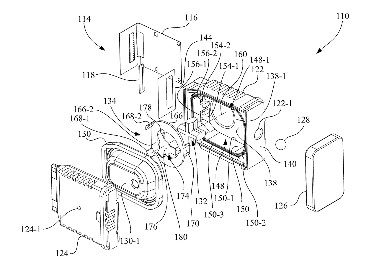
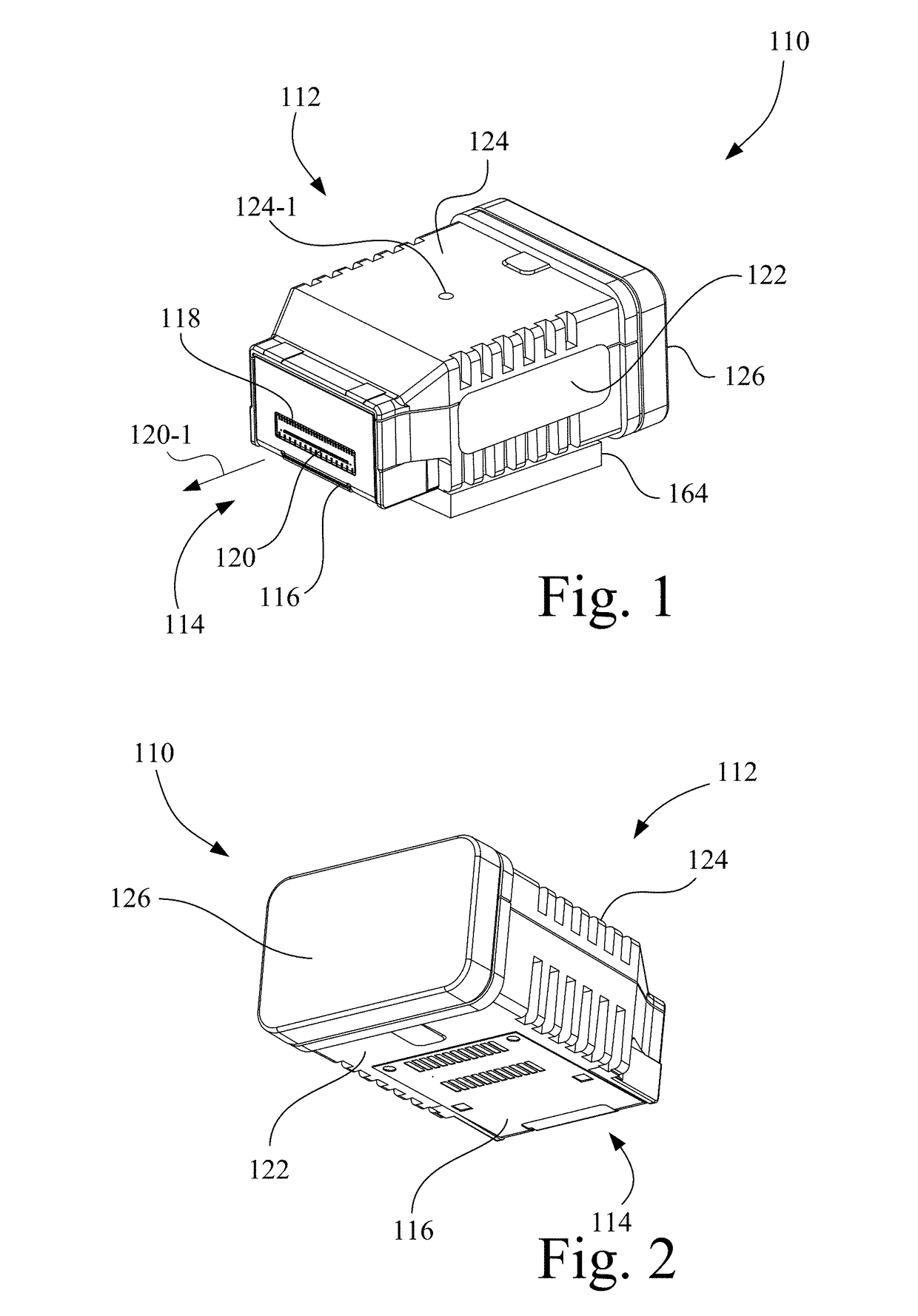
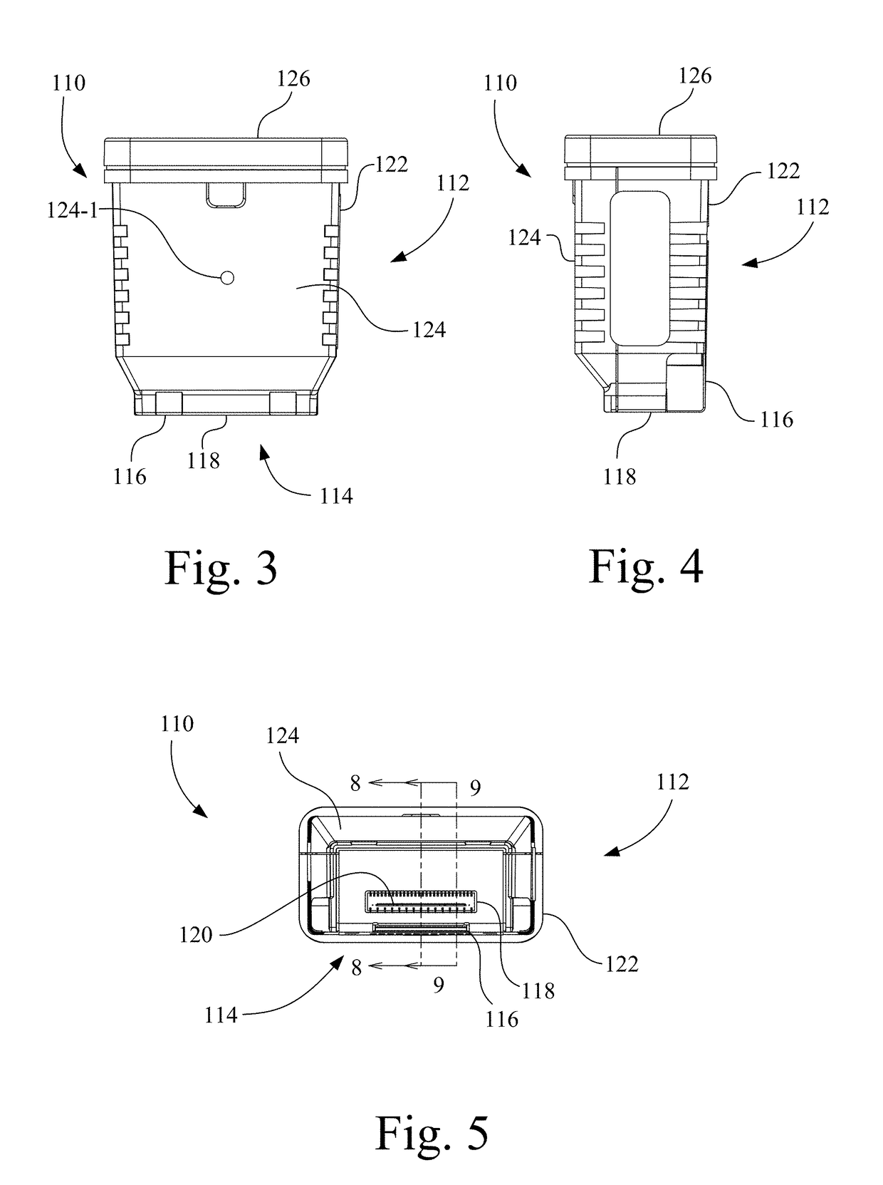
[0074]Referring now to the drawings, and more particularly to FIGS. 1-16, there is shown a fluidic dispensing device, which in the present example is a microfluidic dispensing device 110 in accordance with an embodiment of the present invention.

[0075]Referring to FIGS. 1-5, microfluidic dispensing device 110 generally includes a housing 112 and a tape automated bonding (TAB) circuit 114. Microfluidic dispensing device 110 is configured to contain a supply of a fluid, such as a fluid containing particulate material, and TAB circuit 114 is configured to facilitate the ejection of the fluid from housing 112. The fluid may be, for example, cosmetics, lubricants, paint, ink, etc.

[0076]Referring also to FIGS. 6 and 7, TAB circuit 114 includes a flex circuit 116 to which an ejection chip 118 is mechanically and electrically connected. Flex circuit 116 provides electrical connection to an electrical driver device (not shown), such as an ink jet printer, configured to operate ejection chip 1...


PUM


Abstract

A fluidic dispensing device includes a fluid reservoir containing fluid. A stir bar is located in the fluid reservoir and has a magnet. A generator generates a rotating magnetic field to interact with the magnet. A controller determines a range of a predetermined phase lag between an angular rotational position of the stir bar and an angular rotational position of the rotating magnetic field, determines a status of a present phase lag based on the range of the predetermined phase lag, and takes predetermined action based on the status.

Description

CROSS-REFERENCE TO RELATED APPLICATIONS[0001]This application is related to U.S. patent application Ser. No. ______.BACKGROUND OF THE INVENTION1. Field of the Invention[0002]The present invention relates to fluidic dispensing devices, and, more particularly, to a method of maintaining a fluidic dispensing device, such as a microfluidic dispensing device, that carries a fluid for ejection.2. Description of the Related Art[0003]One type of microfluidic dispensing device, such as an ink jet printhead, is designed to include a capillary member, such as foam or felt, to control backpressure. In this type of printhead, the only free fluid is present between a filter and the ejection device. If settling or separation of the fluid occurs, it is almost impossible to re-mix the fluid contained in the capillary member.[0004]Another type of printhead is referred to in the art as a free fluid style printhead, which has a movable wall that is spring loaded to maintain backpressure at the nozzles ...

Claims


Application Information

Patent Timeline
IPC IPC(8): B41J2/175
CPCB41J2/175B41J2/04571B41J2/17503B08B3/102B41J2/17513B41J2/1753B41J2/17546B41J2/17553B01F33/452
Inventor MARRA, III, MICHAEL A.KOMPLIN, STEVEN R.
Owner FUNAI ELECTRIC CO LTD
Why Eureka
Try Eureka