Pulverized coal burner and boiler

A pulverized coal burner and pulverized coal technology, which is applied in the direction of burners, burners burning powder fuel, burning with various fuels, etc., can solve the problems of high temperature of the burner, slagging of the burner, etc., and achieve the improvement of uneven distribution average effect

Active Publication Date: 2012-05-16
YANTAI LONGYUAN POWER TECH
View PDF8 Cites 1 Cited by
  • Summary
  • Abstract
  • Description
  • Claims
  • Application Information

AI Technical Summary

Problems solved by technology

The full combustion of pulverized coal in the burner will make the temperature in the burner high, which will easily cause slagging in the burner

Method used


Image

  • Pulverized coal burner and boiler
  • Pulverized coal burner and boiler
  • Pulverized coal burner and boiler

Examples


Embodiment 2

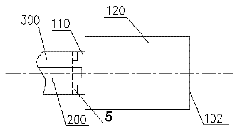
[0042] Please refer to image 3 , which is a schematic structural view of the pulverized coal burner provided in Embodiment 2.

[0043] On the basis of Embodiment 1 of the present invention, the internal combustion chamber 100 of the pulverized coal burner provided by Embodiment 2 includes a main combustion chamber 120 and a deceleration inlet section 110 connected to the front end of the main combustion chamber 120, and the inlet 101 is located at the deceleration inlet section 110 Intersection with the air inlet duct 300.

[0044] A swirl vane 5 may be installed on the inner wall of the deceleration inlet section 110 .

[0045] Such as image 3 As shown, the cross-sectional area of ​​the deceleration inlet section 110 is smaller than the cross-sectional area of ​​the main combustion chamber 120 . When the pulverized coal gas flow enters the main combustion chamber 120 with a large cross-sectional area from the deceleration inlet section 110 with a small cross-sectional ar...


PUM


Abstract

The invention discloses a pulverized coal burner, comprising a heat source and an internal combustion chamber, the heat source is arranged in the internal combustion chamber, the internal combustion chamber is provided with an inlet, a main long cylindrical combustion chamber and an outlet, the heat source can ignite pulverized coal passing through the internal combustion chamber, and enables the pulverized coal to perform incomplete combustion in the internal combustion chamber; a swirl vane is arranged in the internal combustion chamber. In the invention, the pulverized coal burner and a boiler are provided to avoid the coking phenomenon in the internal combustion chamber or on the inner wall of the main combustion chamber and solve the problem of uneven distribution of pulverized coal concentration in the circumferential direction of the internal combustion chamber or the main combustion chamber.

Description

technical field [0001] The invention relates to a pulverized coal combustion technology, in particular to an internal combustion pulverized coal burner and a boiler. Background technique [0002] For a long time, the start-stop and low-load stable combustion of boilers in thermal power generating units have consumed a large amount of fuel oil. According to statistics from the my country Electricity Council, from 2009 to 2015, China's installed power capacity increased by an average of 6,700 kW per year. With the rapid increase in the construction of supercritical parameter units, the fuel consumption for commissioning, start-up and shutdown, and stable combustion will also increase sharply. In response to the "Notice of the State Council on Further Strengthening Fuel-saving and Power-saving Work", at present, most boilers of thermal power generating units have adopted micro-oil ignition technologies such as plasma oil-free and small oil guns, saving a lot of fuel. However,...

Claims


Application Information

Patent Timeline
Patent Type & Authority Applications(China)
IPC IPC(8): F23D1/02F23C5/08
Inventor 王雨蓬唐宏苗雨旺程昌业刘鹏王雨勃张超群龚泽儒崔星源张孝勇张玉斌
Owner YANTAI LONGYUAN POWER TECH
Why Eureka
Try Eureka