Eureka AIR delivers breakthrough ideas for toughest innovation challenges, trusted by R&D personnel around the world.

Moulding process

a moulding and process technology, applied in the field of moulding process, can solve the problems of difficult to meet consumer demand for more bespoke shapes, time-consuming and expensive production of moulds for such a process, commercially viable, etc., and achieves the effect of reducing lead time, cost, and easy recycling after us

Active Publication Date: 2018-03-29
PIXSWEET BV
View PDF0 Cites 5 Cited by
  • Summary
  • Abstract
  • Description
  • Claims
  • Application Information

AI Technical Summary

Benefits of technology

The patent is about using 3-dimensional printing to make plastic mould formers with custom shapes. Typically, these mould formers would cool very slowly, which would significantly decrease production speed. However, this invention proposes using holes to speed up the cooling process. These holes help to release hot air during the forming process, which makes the mould former cool faster. This improves efficiency and reduces waste. The invention also suggests using edible elongate members, which helps to reduce waste and make the end product more desirable. Overall, this invention provides a more efficient and cost-effective way to produce custom plastic mould formers.

Problems solved by technology

The production of the moulds for such a process is time-consuming and expensive, and as a result, is only commercially viable for a design that is long-lived, or is sold in very large numbers.
It is thus difficult to meet consumer demand for more bespoke shapes that might only be required in relatively small numbers.

Method used


Image

  • Moulding process
  • Moulding process
  • Moulding process

Examples


Embodiment Construction

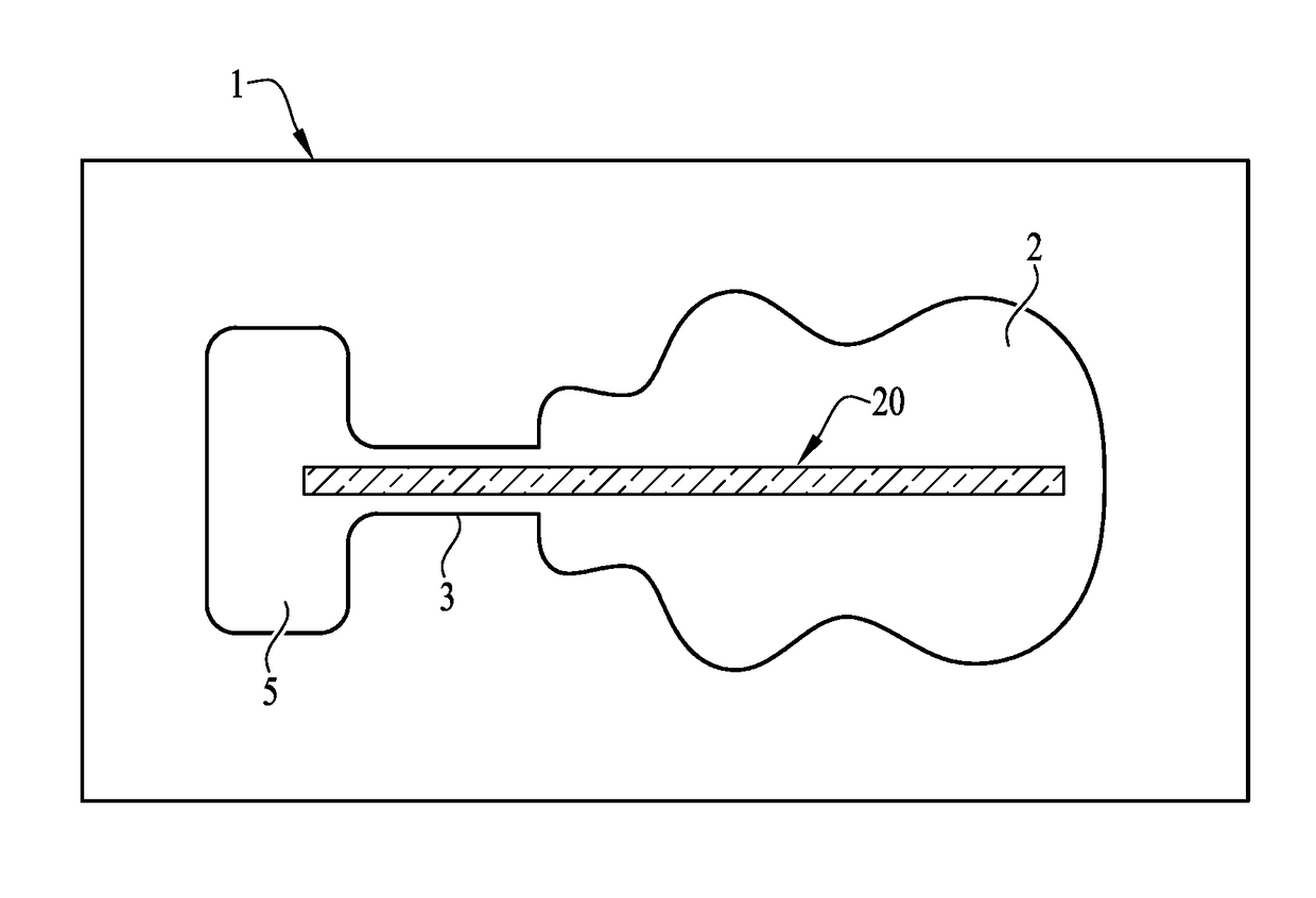
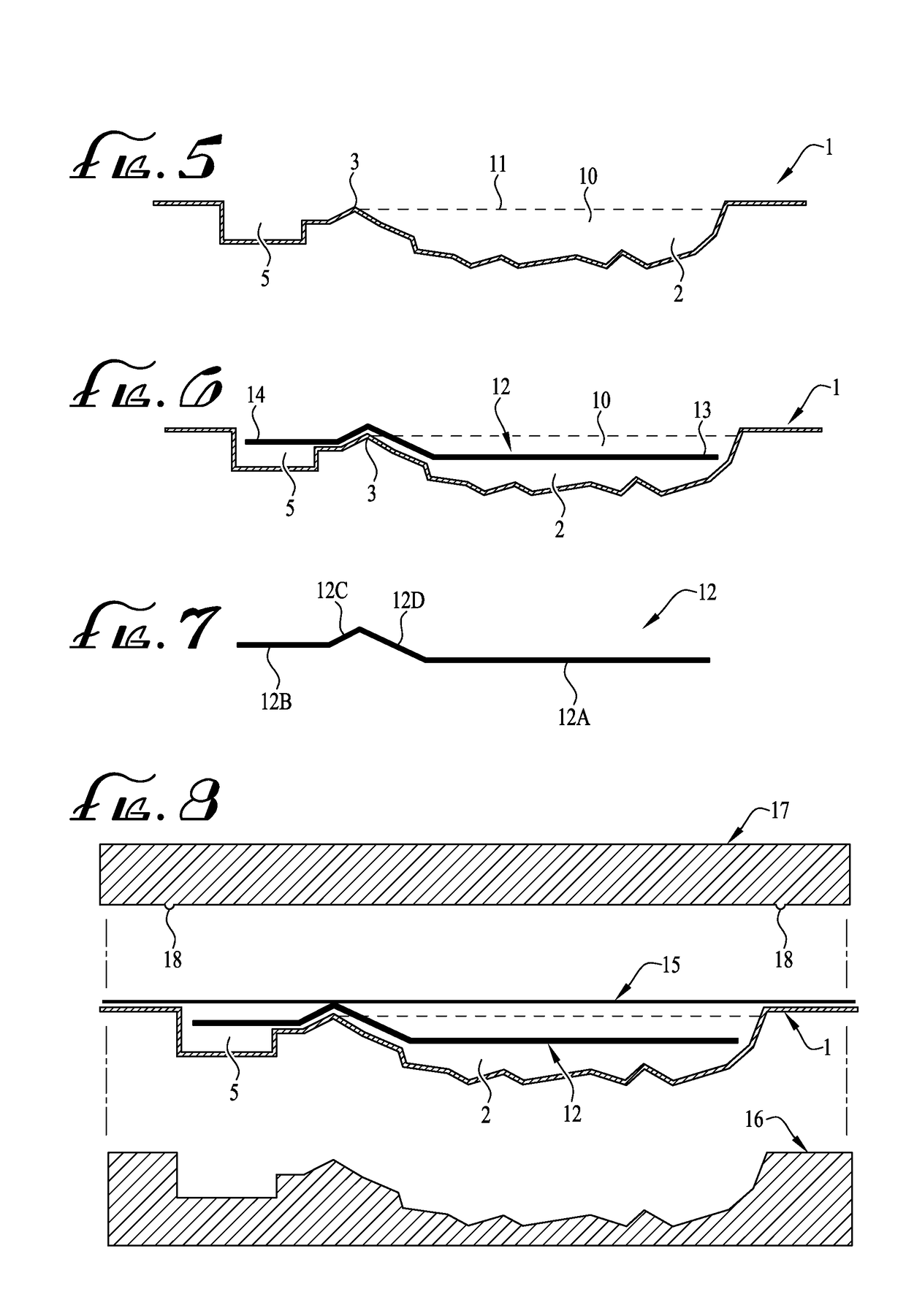
[0054]FIGS. 1 and 2 illustrate, in plan and cross-sectional view respectively, a mould for use in a method of the present invention, generally indicated by 1. The mould 1 has an indentation 2 corresponding to the desired shape of a moulded item to be made. Adjacent one edge of the indentation 2 is a weir 3 that has a height at, or just below the height of the surrounding plane 4 of the mould. In particularly preferred embodiments, the height difference between the top of the weir 3 and the top surface 4 of the mould is approximately the same as the thickness of the elongate member 12 described below. In the embodiment illustrated, the mould further comprises a second indentation 5 adjacent the weir 4, but on the other side to the indentation 2. In some embodiments, the second indentation 5 is not used, but its function will be described below.

[0055]FIGS. 3 and 4 illustrate, in cross-section, a mould former 6 for use in a method of the invention. The mould former 6 is shaped to inclu...


PUM

PropertyMeasurementUnit
Freezing pointaaaaaaaaaa
Phaseaaaaaaaaaa

Abstract

The invention is directed to a method of forming a moulded item said method comprising the steps of (a) providing a mould former comprising an indentation having an inner surface and a bottom face and made of plastics and manufactured by a 3-dimensional printing process, said mould former being shaped to form a mould having (i) an indentation corresponding to the desired shape of said moulded item; and (ii) a series of holes extending between the inner surface and the bottom face of the mould former, (b) forming a mould in said mould former from a plastics material; (c) positioning an elongate member in said mould; (d) introducing a volume of liquid into said indentation; (e) positioning a cover over said mould and sealing it thereto; (f) causing said liquid to solidify.

Description

FIELD OF THE INVENTION[0001]The invention relates to methods for producing moulded items, including confections and frozen confections, candles and other decorative consumer items. The invention particularly relates to methods for producing relatively small numbers of such items in a bespoke fashion, in response to consumer requests.BACKGROUND AND PRIOR ART[0002]Moulded items are very popular in a number of consumer markets. In the food arena, confections such as chocolate-based confections are often produced in novelty shapes, such as in the shape of trees or animals. Also, frozen confections such as frozen fruit composites (often known as “ice pops” or “ice lollies”) or ice-cream are also produced in novelty shapes. In both of these contexts, and especially so in the case of frozen confections, it is common to include a stick, in the form of an rigid elongate member, in the product to allow a consumer to hold the item by the stick, rather than touching the food item itself.[0003]M...

Claims


Application Information

Patent Timeline
IPC IPC(8): B29C33/38A21D13/47A23G1/50A23G3/56A23G9/22A23G9/26B29C39/10B29C67/24B33Y10/00B33Y80/00C11C5/02
CPCB29C33/3842A21D13/47A23G1/507A23G3/566A23G9/221A23G9/26B29C39/10B29C67/241B33Y10/00B33Y80/00C11C5/023A23V2002/00B29K2855/02A23G9/506B29L2031/758A23G9/503B29C33/0011B29C51/30B29C64/118B29C33/3814B29C33/3857B29C33/3807B29C51/10B29K2055/02B29C33/38
Inventor KYTTANEN, JANNE TUOMASZANEN, EDUARD WILLEM
Owner PIXSWEET BV
Why Eureka
Eureka Blog
Learn More