Eureka AIR delivers breakthrough ideas for toughest innovation challenges, trusted by R&D personnel around the world.

Dispatch management platform for nurse call system

a technology of dispatch management and nurse call system, which is applied in the field of dispatch management platform for nurse call system, can solve the problems of patient frustration and dissatisfaction, and the inability of the nurse staff to attend other patients or otherwise be preoccupied, and achieve the effect of efficient deployment of provider sta

Active Publication Date: 2018-03-22
ZUCKERMAN YAIR +1
View PDF12 Cites 13 Cited by
  • Summary
  • Abstract
  • Description
  • Claims
  • Application Information

AI Technical Summary

Benefits of technology

The present invention provides a dispatch management platform that can work with an existing nurse call system to better manage the deployment of provider staff. This platform uses new metrics to track and improve the efficiency of the staff deployment process, and increases the level of automation in the nurse dispatch process. In summary, this invention aims to make the nurse dispatch process more effective and efficient.

Problems solved by technology

However, nursing staff may be busy attending other patients or otherwise be preoccupied.
They may not be aware of the call and there is no assurance that the patient will be attended to in a timely manner.
This is major source of patient frustration and dissatisfaction.
Several studies also show longer call response times contribute significantly to the risk of falling.
Part of the problem is that providers do not use their nurses efficiently.
Modern nurse call systems provide for two-way communication between a patient and a nurse to avoid this, but the existing approach of assigned nurse rounds is not efficient.
However, there is no input from any other users, aside from the nursing staff, nothing from the patient / resident about the call / request, and no capability for integration with other enterprise systems such as records, payroll, etc.
Unfortunately the foregoing references are all concerned with automating, monitoring and enforcing an existing workflow.

Method used


Image

  • Dispatch management platform for nurse call system
  • Dispatch management platform for nurse call system
  • Dispatch management platform for nurse call system

Examples


Embodiment Construction

[0042]The present invention is a nurse call dispatch platform for workflow optimization of the patient nurse call process that creates accountability for patient satisfaction and outcomes.

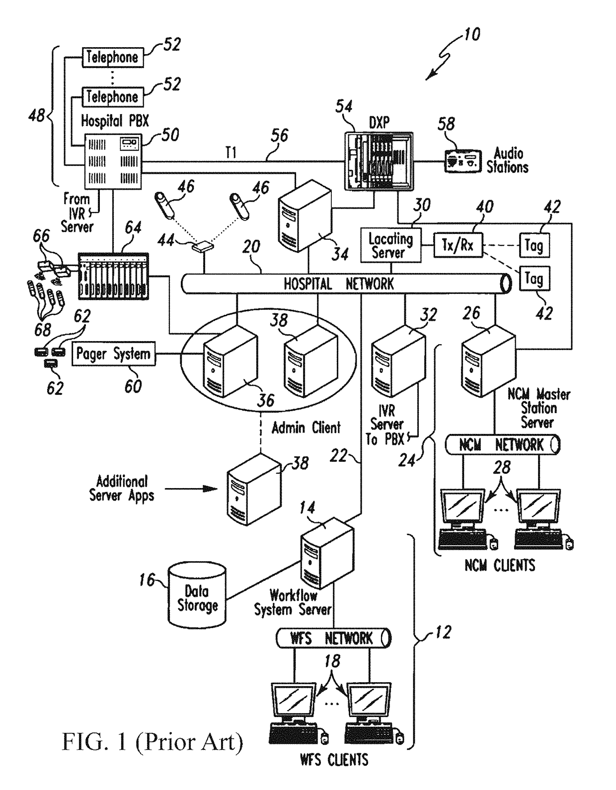
[0043]FIG. 2 is an illustration of the hardware architecture of the present invention integrated with an existing nurse call system such as shown in FIG. 1, the latter typically including a distributed client-server hardware architecture as typically maintained at a healthcare facility. More specifically, the existing architecture may include a nurse call server 14 coupled to hospital network 20, and an RTLS location server 30 in communication with tracking tags 42 mounted to pieces of equipment or carried by nurses. Location server 30 executes software to track these tags 42. Location server 30 associates unique ID data from the tags 42 with ID data, such as an ID number of the carrying nurse.

[0044]In accordance with the workflow of the present invention one person is assigned to the dispatch quar...


PUM


Abstract

A dispatch management computer system that integrates with an existing nurse call system for clinical workflow optimization and to create accountability for patient satisfaction and outcomes. The system integrates a “quarterback” (e.g., dispatcher) tablet with a custom dispatch application that presents a floor plan for tracking the RTLS position of staff members and to provide a visual indication of which room and bed the call originated from. When a patient requests assistance, the QB application presents an assessment of the patient needs and, if further assistance is required, provides the dispatcher tools for real time assignment of the appropriate staff member and dispatch to begin the task within a predetermined amount of time required to complete the task allocated. The system enables the prompt assignment of staff personnel and assures that a patient receives prompt staff attention.

Description

CROSS-REFERENCE TO RELATED APPLICATION(S)[0001]The present application derives priority from U.S. Provisional Patent Application 62 / 494,378 filed 8 Aug. 2016.BACKGROUND OF THE INVENTION1. Field of the Invention[0002]The present invention relates to a computer system and method for responding to nurse calls in a healthcare setting and, more particularly, to a nurse call assurance platform for clinical workflow optimization that creates accountability for patient satisfaction and outcomes.2. Description of the Background[0003]Hospitals, outpatient facilities, and nursing facilities all share a common need for improving the time it takes in responding to the patient needs and requests. Because of the current procedures. Typically patients will use a nurse call button to summon assistance. In most facilities this triggers a visual indication over the patient's room and a call indication at the nurse station. However, nursing staff may be busy attending other patients or otherwise be pre...

Claims


Application Information

Patent Timeline
Patent Type & Authority Applications(United States)
IPC IPC(8): G08B25/00G08B25/01G08B21/18
CPCG08B25/001G08B25/016G08B21/182H04W76/50G16H40/20A61B5/747
Inventor ZUCKERMAN, YAIRROBESON, NATHANIEL
Owner ZUCKERMAN YAIR
Why Eureka
Eureka Blog
Learn More