
A method and system for georeferencing underground data

a georeferencing system and underground data technology, applied in the field of georeferencing underground data, can solve the problems of drift error, scanner on its own, no way of knowing its location within an externally-defined co-ordinate system,

Active Publication Date: 2018-03-22
PECK TECH CONSULTING
View PDF6 Cites 4 Cited by
  • Summary
  • Abstract
  • Description
  • Claims
  • Application Information

AI Technical Summary

Benefits of technology

The present invention provides an improved georeferencing system that aligns laser scanned data with an external coordinate frame and corrects accumulated drift error. The system uses a sparse set of surveyed control points, and a computer processor records the information about each control point and aligns other scanned data to the recorded data. The alignment is done by performing a best-fit transformation on the other scanned data using a least-squares method. The data acquiring means may include laser scanners, RFID tags, retro-reflective LIDAR targets, Wi-Fi access points, bar codes, sonar, calibrated cameras, radar, flash LIDAR, and MEMS LIDAR. The invention allows for more accurate and efficient georeferencing in underground geometric data.

Problems solved by technology

However, the scanner, on its own, has no way of knowing its location within an externally-defined co-ordinate system.
One known error in positioning systems is drift error.
Drift error refers to error in a scanner's estimated location that accumulates with time and / or distance.
Drift error results in a distorted output point cloud—a problem that is not corrected by simply aligning the point cloud with a mine coordinate system.
If a rigid transformation were performed, it would result in a map that was aligned with the external coordinate system but may still contain discrepancies.
Drift error is inherent in any mobile system that computes its location incrementally.
However, systems being used underground cannot use GPS in this manner because there is no GPS satellite signal underground.
However, closed scan loops are difficult to make work without manual input and because they are often impractical in real mines.
Since the above systems are dependent on the GPS for positioning and error correction, they are not intended to operate in environments where GPS signals are unavailable.
However, such a method is not practical for long-term or deep underground use.
In mobile robotics, the “data association problem” is the problem of deciding which acquired measurements (or which parts of a map) correspond to which known points in the real world.
However, this method has a disadvantage of requiring input in the form of manually-chosen anchor points (typically by a user clicking points on a computer display and manually defining them to be associated).
However, this hypothetical new method would have the disadvantage of requiring dense surveyed data in all areas before it's possible to georeference there.
This makes it less useful for the case where the goal is to use the scanner to “fill in gaps” and reduce the total amount of survey work necessary.

Method used


Image

  • A method and system for georeferencing underground data
  • A method and system for georeferencing underground data
  • A method and system for georeferencing underground data

Examples


Embodiment Construction

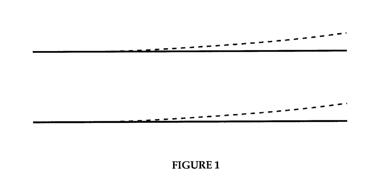
[0047]Referring to FIG. 1, a solid outline representing a top-down view of a portion of a mine is shown. The dashed outline represents a map created using a mobile scanner exhibiting drift error. This map is aligned (georeferenced), but still contains drift error.

[0048]The method of the invention includes two phases: (i) a control point profiling, and (ii) nonrigid transformation. The advantage of nonrigid transformation is that it may be used for georeferencing and / or error correction while rigid transformation may be used for georeferencing only. Each of the above two phases is now described more fully.

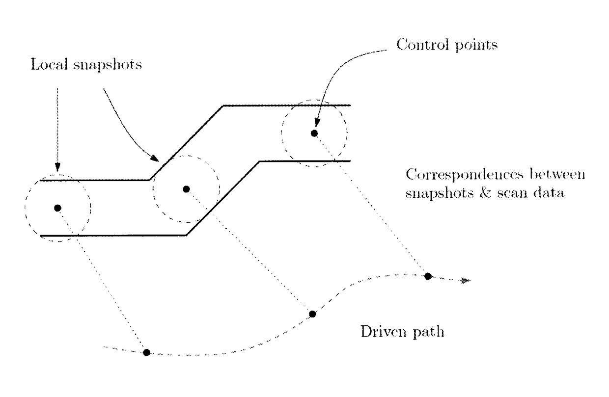
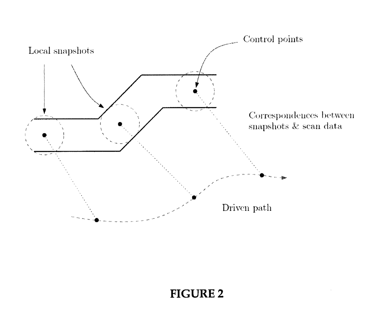
[0049]Control point (tag) profiling is the process of visiting each control point with a laser scanner and recording a “snapshot” of the local area. This part of the process therefore obtains a set of easily-recognizable and globally-positioned landmarks that can be used to georeference subsequently scanned data. For each control point:[0050]1. a laser scanner is precisely aligned w...


PUM


Abstract

Known georeferencing techniques require input in the form of manually-chosen anchor points or dense surveyed data. The present invention is an improved method and system for georeferencing underground geometric data. The method comprises (a) visiting at least two control points; (b) obtaining information about each of the at least two control points using scanning means; (c) recording the information about the at least two control points into a computer processor; and (d) performing a best-fit transformation to the recorded information. Preferably, the scanning means comprises laser scanners and at least two radio-frequency identification (RFID) tags. However, other technologies, such as retro-reflective LIDAR targets, Wi-Fi access points or bar codes and a bar code reader may also be used. In addition, sonar, radar, flash LIDAR, MEMS LIDAR, or any other similar technology could be used.

Description

TECHNICAL FIELD OF THE INVENTION[0001]The invention relates to a method and system for georeferencing underground data.BACKGROUND[0002]Most underground mines use a mine coordinate system to consistently represent all surveyed quantities (e.g., the precise location of all mine tunnels, features, infrastructure, etc.). In order to track and locate the position of underground equipment, laser scanning technology may be used. However, the scanner, on its own, has no way of knowing its location within an externally-defined co-ordinate system.[0003]One known error in positioning systems is drift error. Drift error refers to error in a scanner's estimated location that accumulates with time and / or distance. Drift error results in a distorted output point cloud—a problem that is not corrected by simply aligning the point cloud with a mine coordinate system. The fact that the map contains drift error is an important distinction when compared to stationary LIDAR scans, which are collected fro...

Claims


Application Information

Patent Timeline
IPC IPC(8): G01V11/00G06K7/10
CPCG01V11/002G06K7/10366E21F17/00G01C7/06G01S13/86G01S13/74G01S13/885G01C15/002G01S17/89G01S7/4808G01S17/86
Inventor PYKE, SANDY WAYNEMARSHALL, JOSHUA ALEXANDERLAVIGNE, NICHOLAS JAMESARTAN, UNAL
Owner PECK TECH CONSULTING
Learn More