
Autonomous underwater vehicle combined navigation system

A combined navigation system and underwater robot technology, applied in surveying and navigation, radio wave measurement system, navigation through speed/acceleration measurement, etc., can solve the problem of inapplicable local sea area accurate autonomous navigation, scanning imaging sonar can not achieve autonomy Navigation and other issues

Active Publication Date: 2011-05-04
OCEAN UNIV OF CHINA
View PDF4 Cites 62 Cited by
  • Summary
  • Abstract
  • Description
  • Claims
  • Application Information

AI Technical Summary

Problems solved by technology

[0004] For this reason, sonar technology is applied to AUVs. Scanning sonar has better imaging capabilities. Scanning sonar can be used in conjunction with medium-precision inertial navigation sensors to meet autonomous navigation and positioning, and there is no need to use expensive high-precision inertial systems. The manufacturing cost of AUV is reduced. For a large-scale underwater environment, scanning imaging sonar and internal sensors can realize large-scale global autonomous navigation, but it is not suitable for precise autonomous navigation in local sea areas, especially when the terrain of local sea areas When the terrain is complex, the scanning imaging sonar may not be able to realize the function of autonomous navigation

Method used


Image

  • Autonomous underwater vehicle combined navigation system
  • Autonomous underwater vehicle combined navigation system
  • Autonomous underwater vehicle combined navigation system

Examples


Embodiment Construction

[0023] The present invention will be further described below in conjunction with the accompanying drawings.

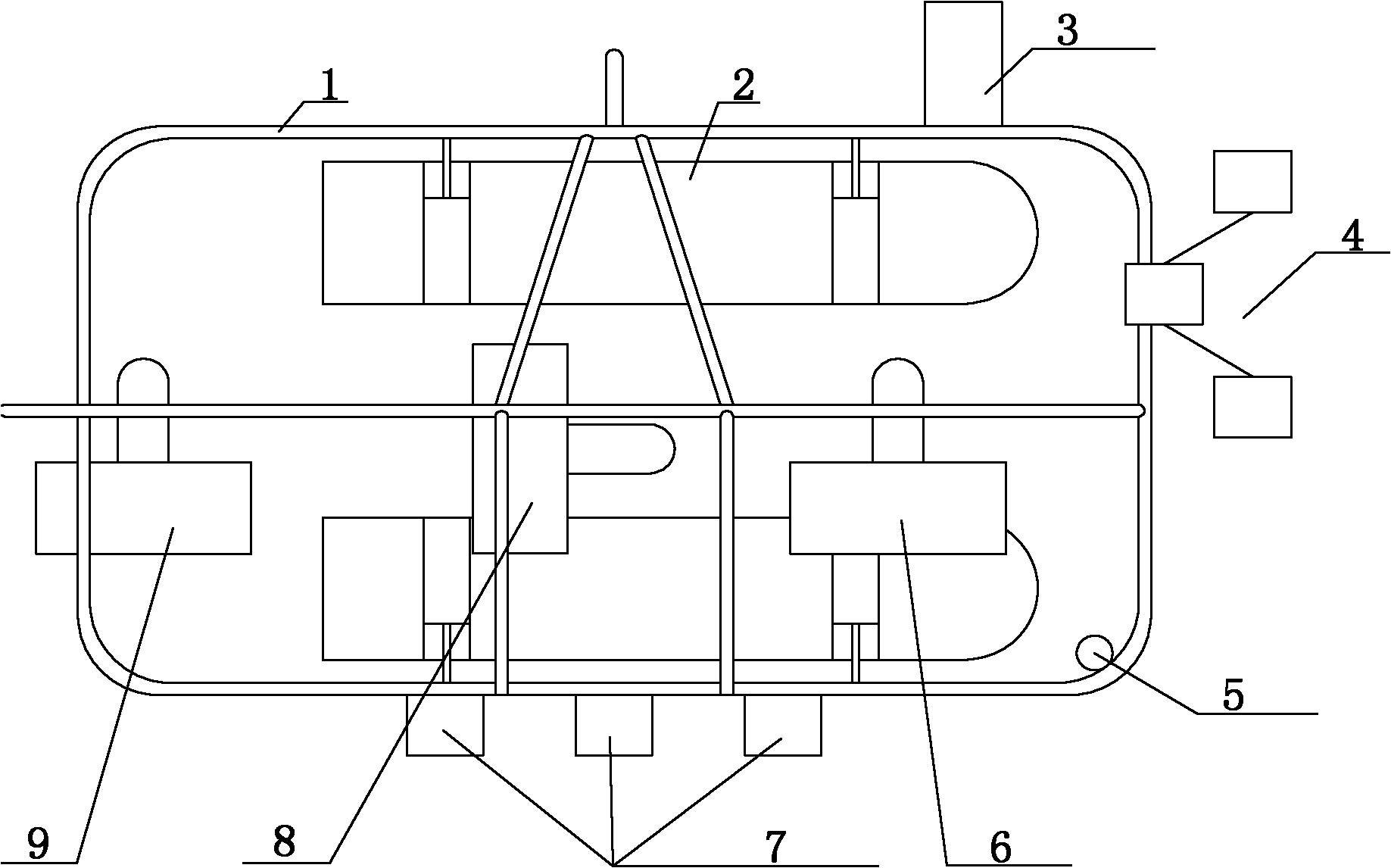
[0024] Such as figure 1 Shown is the autonomous underwater vehicle of the present invention. The robot adopts an open-frame mechanical structure. The upper and lower double-layer pressure chambers 2 are fixed on the outer frame 1, and five underwater propellers are set, including three vertical propellers and two horizontal propellers 8. The left and right symmetrical sides of the portion are respectively provided with a vertical propeller 6, and the left and right symmetrical sides of the middle part of the outer frame 1 are respectively fixed with a horizontal direction propeller 8; There is a vertical direction propeller 9, and pressure sensor is installed on the top of this propeller.

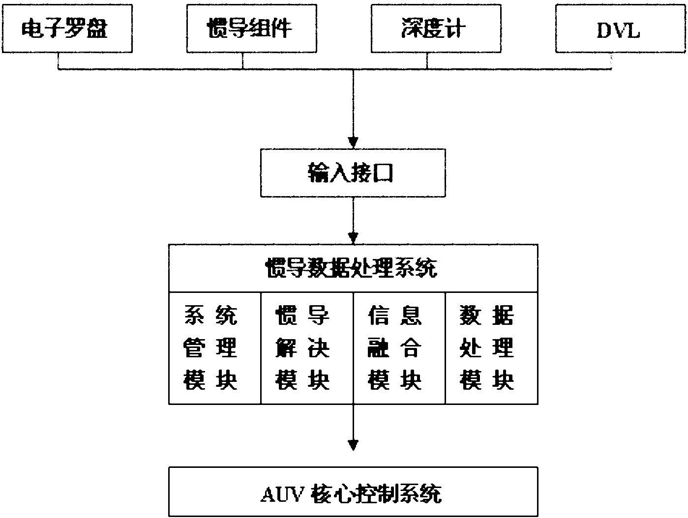
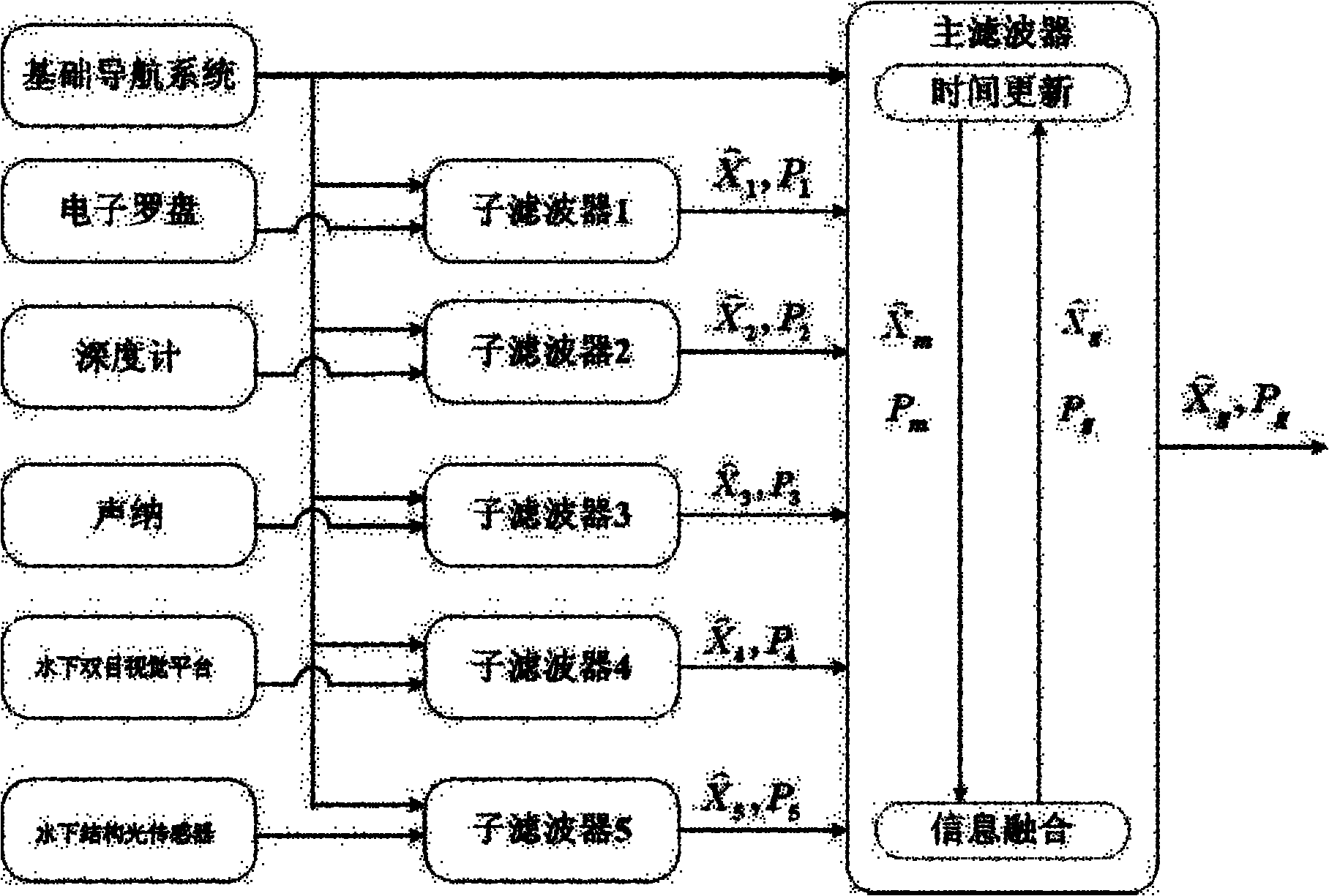
[0025]The navigation system of the autonomous underwater robot includes an inertial-based navigation device and an external sensor navigation device, wherein the inertial-based na...


PUM


Abstract

The invention relates to an underwater vehicle navigation system, in particular to an autonomous underwater vehicle combined navigation system. The system comprises an inertia basis navigation device and an external sensor navigation device, wherein the inertia basis navigation device comprises a Doppler velocimeter, an optical fiber gyro, a pressure sensor, an electronic compass and a depthometer; and the external sensor navigation device comprises a sonar. The combined navigation system also comprises an underwater structure optical sensor and an underwater binocular vision platform, wherein the underwater structural optical sensor comprises a forward-vision structure optical sensor positioned on the front of an outer frame of an autonomous underwater vehicle, and a downward-vision structure optical sensor positioned at the bottom of the outer frame; the underwater binocular vision platform comprises a forward-vision binocular vision platform positioned on the front of the outer frame, and a downward-vision binocular vision platform positioned at the bottom of the outer frame; the forward-vision structure optical sensor and the forward-vision binocular vision platform form a forward-vision structure optical and visual system module positioned on the front of the outer frame; and the downward-vision structure optical sensor and the downward-vision binocular vision platform form a downward-vision structure optical and visual system module positioned at the bottom of the outer frame.

Description

technical field [0001] The invention relates to an underwater robot navigation system, in particular to an autonomous underwater robot combined navigation system. Background technique [0002] Inertial navigation is the main positioning method used by autonomous underwater vehicles (AUV) for autonomous navigation underwater, but its main problem is that when the accuracy can meet the requirements, the price is often too expensive. Due to the advancement of sonar technology, the current more advanced AUV basically does not use an accelerometer but a Doppler velocimeter, which can directly measure the 3D velocity of the AUV relative to the seabed without integration. Using the navigation method combining Doppler speedometer and fiber optic gyroscope, it still inevitably produces cumulative errors, and its navigation accuracy is 0.2% of the voyage. In order to eliminate this deviation, the main methods currently used are: (1) Use GPS correction, that is, let the AUV float up a...

Claims


Application Information

Patent Timeline
Patent Type & Authority Applications(China)
IPC IPC(8): G01C21/16G01S15/89G01C11/00
Inventor 魏志强殷波丛艳平贾东宁刘兵潘学松
Owner OCEAN UNIV OF CHINA
Learn More