
Dynamic movable integrated system for waste collection

a waste collection and integrated system technology, applied in the field of waste, can solve the problems of low compaction percentage, waste traceability, inefficient current system, and low efficiency of waste collection,

Active Publication Date: 2018-03-15
DALLARMI PIETRO
View PDF3 Cites 3 Cited by
  • Summary
  • Abstract
  • Description
  • Claims
  • Application Information

AI Technical Summary

Benefits of technology

The present invention is a movable waste collection system that includes a container structure with multiple access doors to waste collection containers. The container structure integrates waste compaction means and transferring compacted waste into the containers. The lower portion of the container can be installed in a trench in the ground and can be easily accessed mechanized gripping means. The waste collection containers are modular and can be joined together to create a two-dimensional structure. The system also includes compaction means with a movable bulkhead and thrust bulkheads, as well as seal rings and sensor means for real-time monitoring of the collection containers. The system can also include waste volume reduction means such as round balers, shredders, screw or roller compactors, and briquetting machines. The invention allows for efficient waste collection and reduction.

Problems solved by technology

The current systems have a low compaction percentage and are inefficient for some types of waste, such as organic, plastic and EPS, among others.
Conventional street collection does not involve set times / types during the waste insertion period, but it has various problems; first of all, it is poorly differentiated and often causes city traffic, and then there is the problem of waste traceability, and of the quantities inserted therein.
Substantially, the load of the waste is poorly traced and not well optimized.
Door-to-door collection works well with regard to differentiation, but involves set-time / type insertions, since the user must comply with collection calendars, timetables, set days and waste type; it is slower and costlier, and also creates difficulties in managing the traceability and the quantity inserted by each user.
The installation and maintenance are very costly, given that the use of powerful actuators—commanded by hydraulic control stations—if present, involve the installation of fixed building works.
The buried separate ecological collection sites require cranes for lifting the waste containers included therein, which causes a considerable increase of costs as well as complex maneuvers.
However, the conventional collection systems do not prevent the so-called “empty run”: with such term, it is intended a collection run carried out by a vehicle in which the operator does not find material for the waste collection.
It is also inferred that there is no uniformity among the various mechanical gripping systems in the separate ecological collection site containers, since these are not based on a single standard in use.
The use of large trucks for unloading the containers becomes difficult, especially on narrow streets, and is therefore inefficient.
In addition, the burying of the separate ecological collection site always causes a considerable installation cost.

Method used


Image

  • Dynamic movable integrated system for waste collection
  • Dynamic movable integrated system for waste collection
  • Dynamic movable integrated system for waste collection

Examples


Embodiment Construction

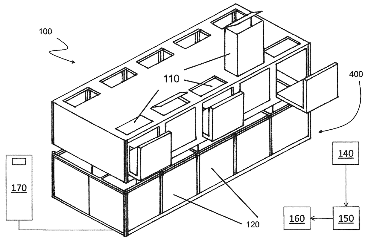
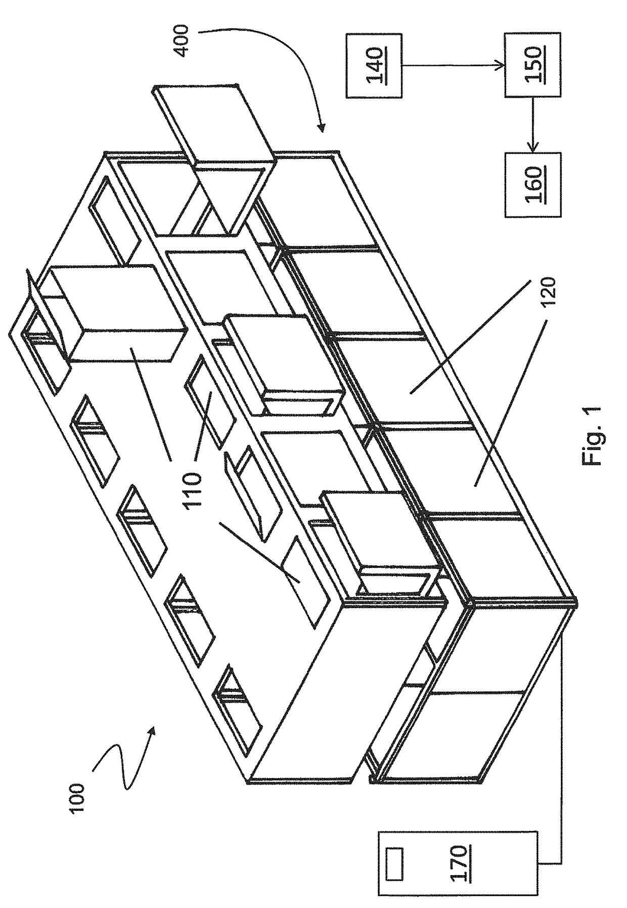
[0032]With reference to the enclosed figures, reference number 100 overall indicates a movable integrated system for waste collection.

[0033]The system 100 comprises a container structure adapted to be installed above ground, which comprises a plurality of access doors 110 to a plurality of collection containers 120 contained in the structure itself, in a manner such that each access door accesses a specific collection container.

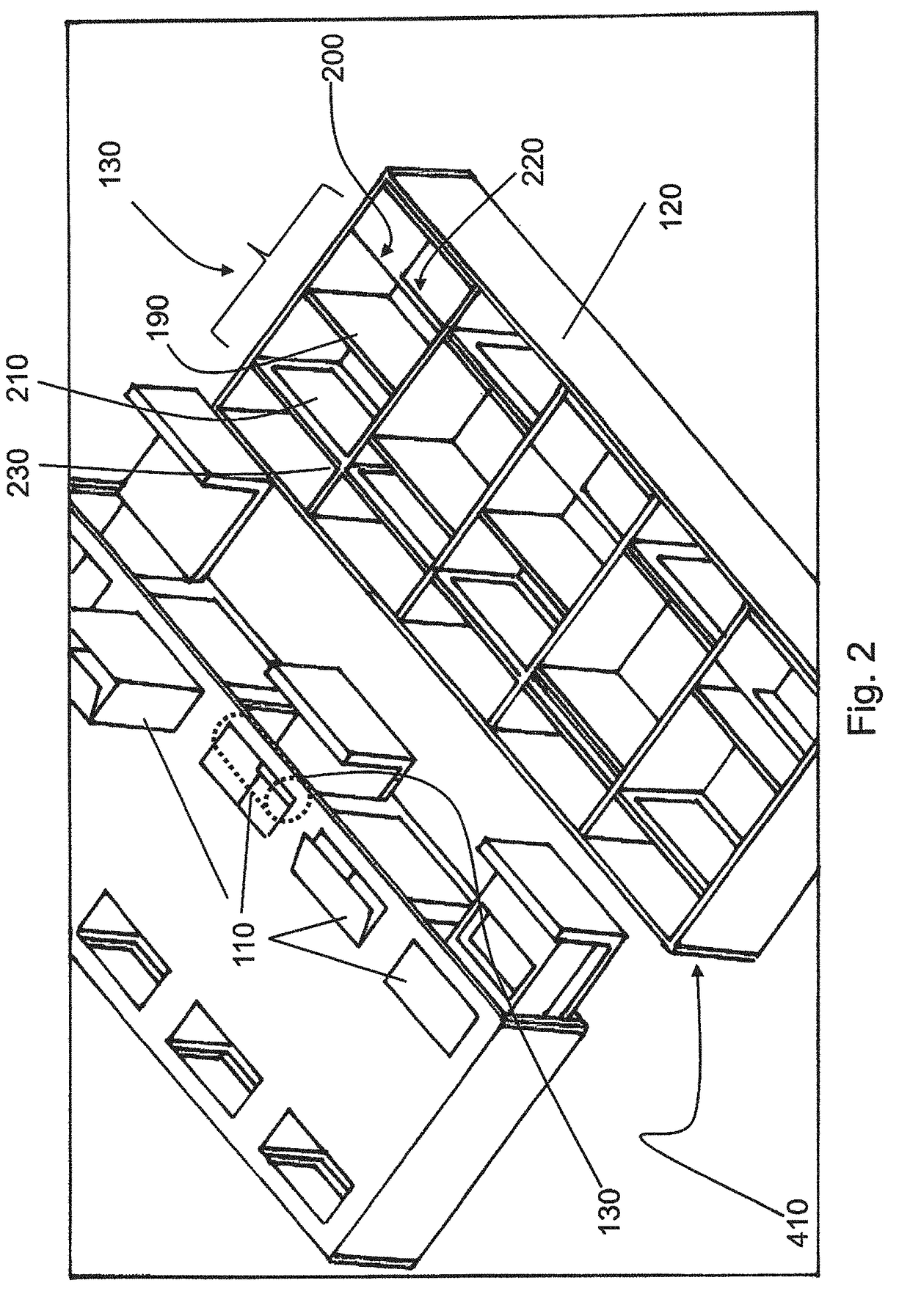
[0034]In detail, the access doors 110 are opened onto an area reserved for the compaction of waste, where compaction means 130 provide for compacting waste, before transferring such waste into the respective collection container 120.

[0035]The compaction means 130 are installed in modules that can be independently extracted with respect to each other. This advantageously allows being able to easily substitute the compaction means 130 in case of failure, or a complete substitution thereof with increasingly innovative solutions, in accordance with the type of wa...


PUM


Abstract

Movable integrated system for waste collection, including a container structure, adapted to be installed at least partially above ground, the structure including a plurality of access doors to a plurality of waste collection compartments or containers contained in the container structure that are made of two-dimensional modular structure; the container structure integrates a waste compaction unit supplied by a respective access hatch and transferring compacted waste into the collection containers.

Description

FIELD OF THE APPLICATION[0001]The present invention regards the field of waste. In detail, the present invention regards a movable integrated system for waste collection.PRIOR ART[0002]Today, waste collection occurs through three methods, due to the use of compactor road vehicles and containers or better yet receptacles, bell-shaped vessels, bins or other items which are specific for waste collection, with the aid of specialized operators for the manual operations of collection, movement and transport of the waste from streets, apartment buildings or collection-assigned areas; the equipment mounted in the chassis is formed by container gripping systems, which are driven by the operator and which unload the waste in a tank of the cradle or casing, through a system which compacts the waste.[0003]The current systems have a low compaction percentage and are inefficient for some types of waste, such as organic, plastic and EPS, among others.[0004]The waste collection systems of known typ...

Claims


Application Information

Patent Timeline
IPC IPC(8): B65F1/00B65F1/14
CPCB65F1/0046B65F1/1447B65F2210/1443B65F2210/128B65F2210/138B65F2210/168B65F2210/162B30B9/3092
Inventor DALL'ARMI, PIETRO
Owner DALLARMI PIETRO
Learn More