
Self-Tuning Microelectromechanical Impedance Matching Circuits and Methods of Fabrication

a microelectromechanical and impedance matching technology, applied in the field of self-tuning microelectromechanical impedance matching circuits and methods of fabrication, can solve the problems of significant insertion loss, performance degradation across frequencies, and difficulty in real-time tuning

Active Publication Date: 2018-03-08
DUEWEKE MICHAEL J
View PDF0 Cites 2 Cited by
  • Summary
  • Abstract
  • Description
  • Claims
  • Application Information

AI Technical Summary

Benefits of technology

The present invention relates to a self-tuning microelectromechanical circuit that can automatically adjust its impedance to match an external AC signal. The circuit includes a first tunable reactance element and a second tunable or fixed reactance element, which are connected in series or in parallel. The first reactance element has a tunable reactance that can be adjusted using a DC signal, while the second reactance element has a fixed reactance. The circuit can be fabricated using a silicon substrate and can be used in various devices such as antennas, energy storage devices, and piezoelectric resonators. The technical effect of the invention is to provide a self-tuning circuit that can automatically adjust its impedance to match an external AC signal, making it easier to connect and use with other devices.

Problems solved by technology

RF antennas are increasingly required to operate over wider ranges of frequencies, resulting in performance degradation across frequencies.
Lumped matching networks provide discrete frequency filtering but suffer from significant insertion loss and are difficult to tune in real time.
In addition, energy harvesting and inductively coupled power transfer circuits are sensitive to impedance matching but do not employ economically viable methods to self-tune impedance to maximize power transfer.

Method used


Image

  • Self-Tuning Microelectromechanical Impedance Matching Circuits and Methods of Fabrication
  • Self-Tuning Microelectromechanical Impedance Matching Circuits and Methods of Fabrication
  • Self-Tuning Microelectromechanical Impedance Matching Circuits and Methods of Fabrication

Examples


Embodiment Construction

[0035]Reference will now be made in detail to various embodiments of the invention, examples of which are illustrated in the accompanying drawings. While the invention will be described in conjunction with the following embodiments, it will be understood that the descriptions are not intended to limit the invention to these embodiments. On the contrary, the invention is intended to cover alternatives, modifications and equivalents that may be included within the spirit and scope of the invention as defined by the appended claims. Furthermore, in the following detailed description, numerous specific details are set forth in order to provide a thorough understanding of the present invention. However, it will be readily apparent to one skilled in the art that the present invention may be practiced without these specific details. In other instances, well-known methods, procedures, components, and circuits have not been described in detail so as not to unnecessarily obscure aspects of th...


PUM


Abstract

A self-tuning impedance-matching microelectromechanical (MEMS) circuit, methods for making and using the same, and circuits including the same are disclosed. The MEMS circuit includes a tunable reactance element connected to a first mechanical spring, a separate tunable or fixed reactance element, and an AC signal source configured to provide an AC signal to the tunable reactance element(s). The reactance elements comprise a capacitor and an inductor. The AC signal source creates an electromagnetically energy favorable state for the tunable reactance element(s) at resonance with the AC signal. The method of making generally includes forming a first MEMS structure and a second mechanical or MEMS structure in / on a mechanical layer above an insulating substrate, and coating the first and second structures with a conductor to form a first tunable reactance element and a second tunable or fixed reactance element, as in the MEMS circuit.

Description

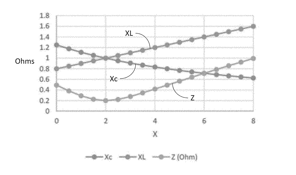
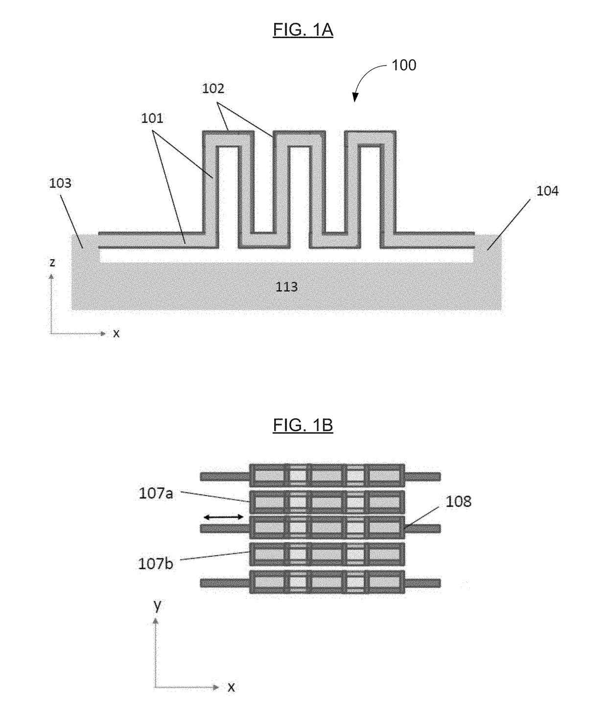
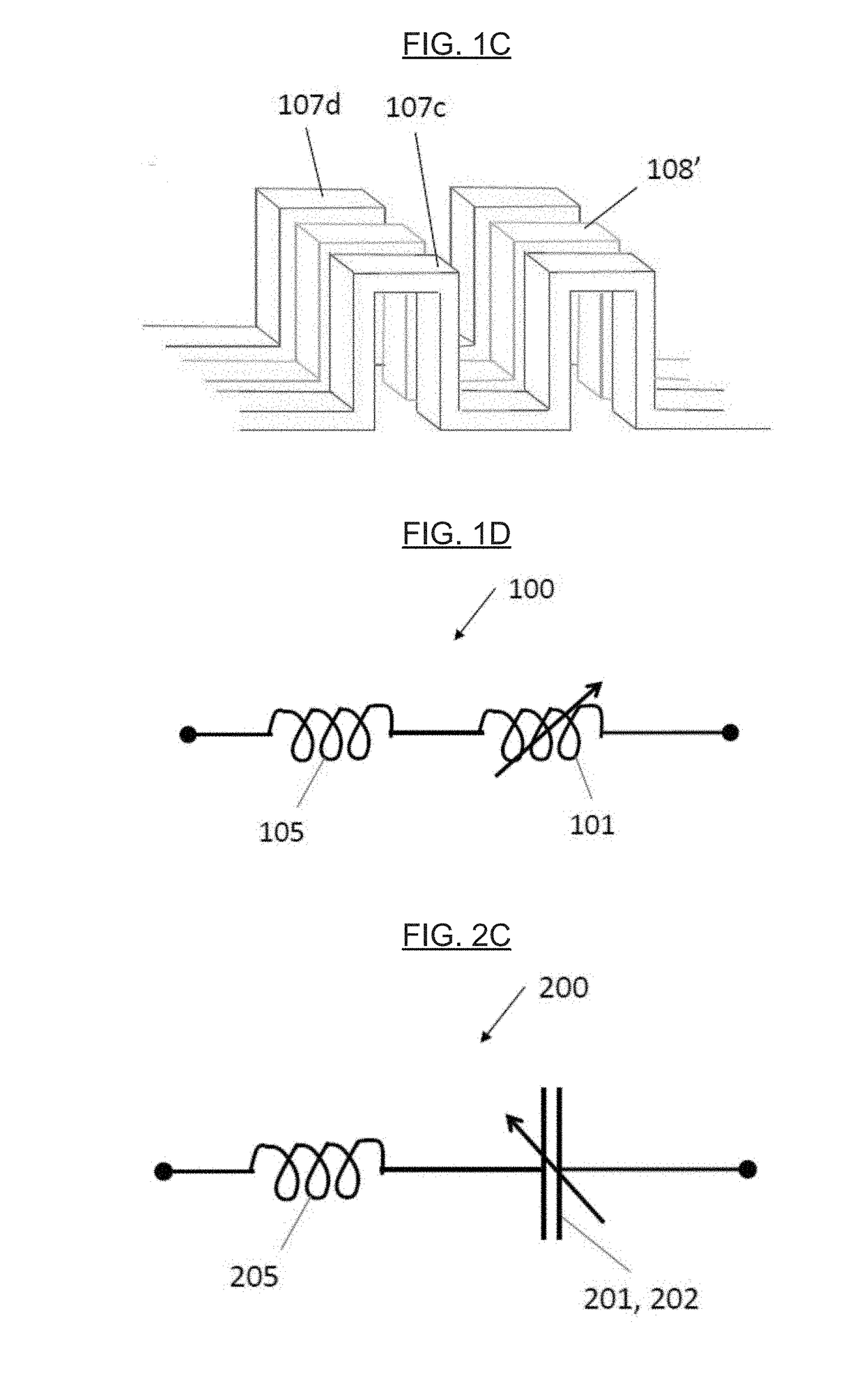
CROSS REFERENCE TO RELATED APPLICATION(S)[0001]This application claims the benefit of U.S. Provisional Patent Application No. 62 / 384,657, filed on Sep. 7, 2016, incorporated herein by reference as if fully set forth herein.FIELD OF THE INVENTION[0002]Self-tuning microelectromechanical impedance matching circuits are disclosed. The microelectromechanical circuit has at least one electromagnetically tunable reactance device connected to a first mechanical spring. In a preferred embodiment, the self-tuning microelectromechanical circuit has at least one electromagnetically tunable capacitor element connected to a first mechanical spring and at least one electromagnetically tunable inductor element connected to a second mechanical spring in which the tunable inductor element and tunable capacitor element are connected electrically. The self-tuning microelectromechanical impedance matching circuit has an unloaded self-resonant frequency omega_UL=1 / SQRT(L_o*C_o) where L_o is the equilibri...

Claims


Application Information

Patent Timeline
IPC IPC(8): H03B5/36B81B3/00B81C99/00H03H7/38G01C19/5755H01L23/64H01L49/02
CPCH03B5/364B81B3/0086B81C99/003H01L28/60H03H7/38G01C19/5755H01L23/642B81B3/0051H03H3/0077H03H7/0115H03H7/175H03H7/1766H03H7/383H03H7/40H03H7/46H03H9/0004H03H9/70H03H2001/0021H03H2007/008H03H2007/386H03H2009/02165
Inventor DUEWEKE, MICHAEL J.
Owner DUEWEKE MICHAEL J
Learn More