Index matching layers
- Summary
- Abstract
- Description
- Claims
- Application Information
AI Technical Summary
Benefits of technology
Problems solved by technology
Method used
Image
Examples
example 1
[0062]With reference to FIGS. 4 and 8-10, a Design 1a of the inventive index matching system was modeled. With reference to FIGS. 8 and 9, the Design 1a employed the index matching system 12 formed of a first layer 22 having a thickness of 4.2 nanometers of ZrO2 applied directly on the surface 18 of the lens substrate 14 (FIG. 3); a second layer 24 having a thickness of 40.0 nanometers of SiO2 applied directly on a surface 26 of the first layer 22; and a third layer 28 having a thickness of 6.3 nanometers of ZrO2 applied directly on a surface 30 of the second layer 24. A surface 32 of the index matching system 12 is a surface upon which the hard-coating 16 is applied or otherwise formed.
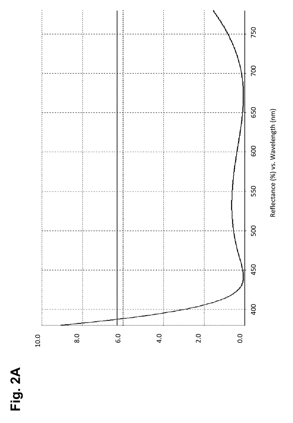
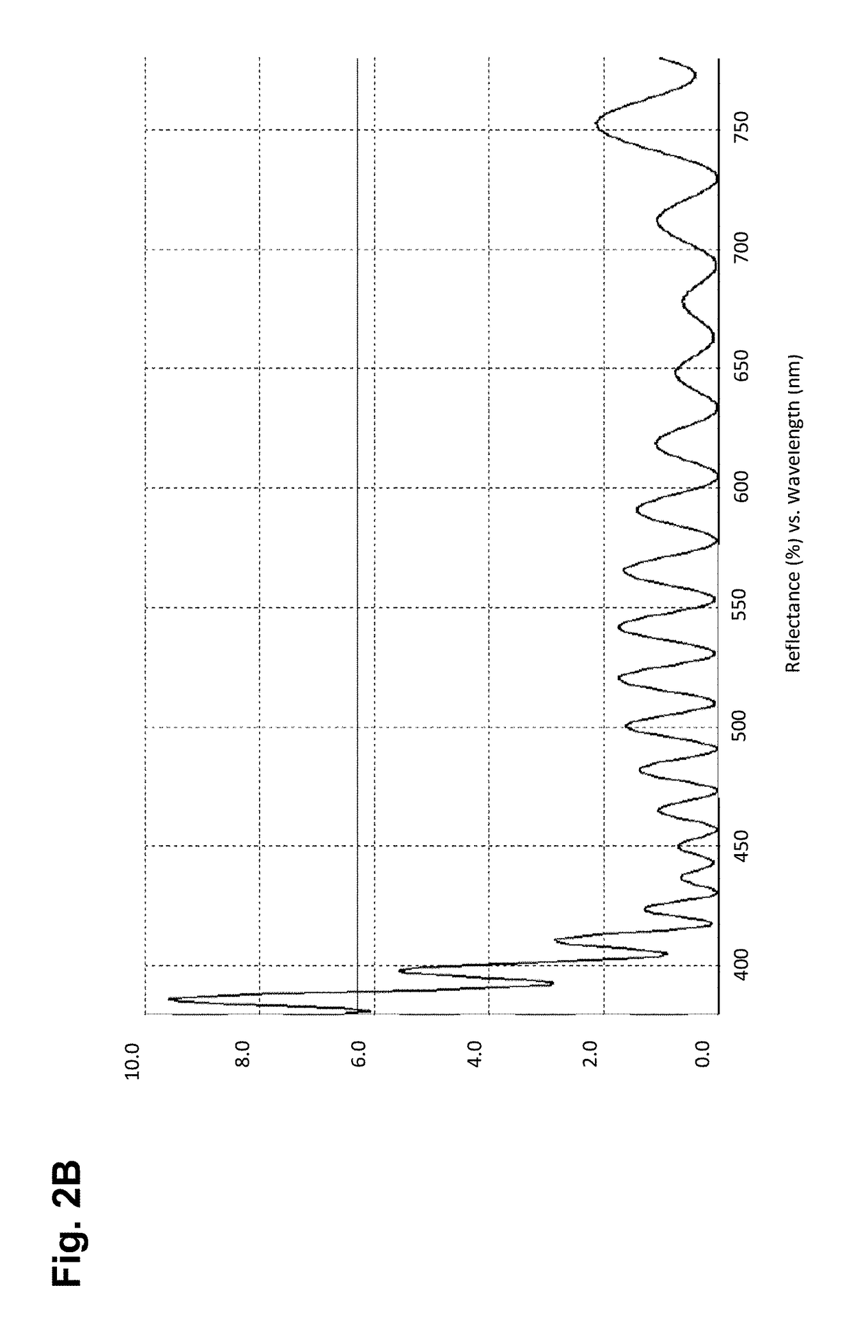
[0063]FIG. 10 compares the modeled reflection spectra for (1) a lens employing the above described inventive index matching system 12, Design 1a, disposed between a 1.67 index lens substrate 14 and a 1.5 index, mismatched hard-coating 16; (2) a lens employing a 1.67 index lens substrate 14 with an in...
example 2
[0064]With reference to FIGS. 4, 8, 11, and 12, a Design 1b of the inventive index matching system was modeled. With reference to FIG. 11, the Design 1b employed the index matching system 12 formed of a first layer 22 having a thickness of 7.0 nanometers of ZrO2 applied directly on the surface 18 of the lens substrate 14 (FIG. 3); a second layer 24 having a thickness of 50.0 nanometers of SiO2 applied directly on a surface 26 of the first layer 22; and a third layer 28 having a thickness of 6.3 nanometers of ZrO2 applied directly on a surface 30 of the second layer 24. A surface 32 of the index matching system 12 is a surface upon which the hard-coating 16 is applied or otherwise formed.
[0065]FIG. 12 compares the modeled reflection spectra for (1) a lens employing the above described index matching system of Design 1a, disposed between a 1.67 index lens substrate 14 and a 1.5 index, mismatched hard-coating 16; (2) a lens employing the above described index matching system of Design ...
example 3
[0067]FIGS. 13A and 13B show photographs comparing two 1.70 index lenses one employing the inventive index matching system (FIG. 13B) and the other lens not employing the inventive index matching system (FIG. 13A). Both lenses shown have a commercially available UV curable 1.5 index (approximate) backside hard-coating (for example UV-NV; Ultra Optics) applied as an outer most layer.
[0068]The benefit of the index matching system of the present invention is immediately obvious from comparison of FIGS. 13A and 13B. In the standard mismatched index lens and hard-coating configuration (FIG. 13A) there are many colored fringes of irregular shapes that are tightly packed. This effect detracts from the appearance of the lens. With the inventive index matching system described above employed between the hard-coating and the lens surface (FIG. 13B), the number of fringes is greatly reduced and are spaced much further apart, hence, significantly improving the appearance of the lens.
PUM
 Abstract
Description
Claims
Application Information
 - R&D
- Intellectual Property
- Life Sciences
- Materials
- Tech Scout
- Unparalleled Data Quality
- Higher Quality Content
- 60% Fewer Hallucinations
Browse by: Latest US Patents, China's latest patents, Technical Efficacy Thesaurus, Application Domain, Technology Topic, Popular Technical Reports.
© 2025 PatSnap. All rights reserved.Legal|Privacy policy|Modern Slavery Act Transparency Statement|Sitemap|About US| Contact US: help@patsnap.com


