
Method of manufacturing film with a coating layer

a technology of coating layer and manufacturing method, which is applied in the direction of electric/magnetic/electromagnetic heating, instruments, optical elements, etc., can solve the problems of interference fringe, deterioration of display visibility, and peeled anti-reflection film or damag

Inactive Publication Date: 2014-11-25
FUJIFILM CORP
View PDF13 Cites 1 Cited by
  • Summary
  • Abstract
  • Description
  • Claims
  • Application Information

AI Technical Summary

Benefits of technology

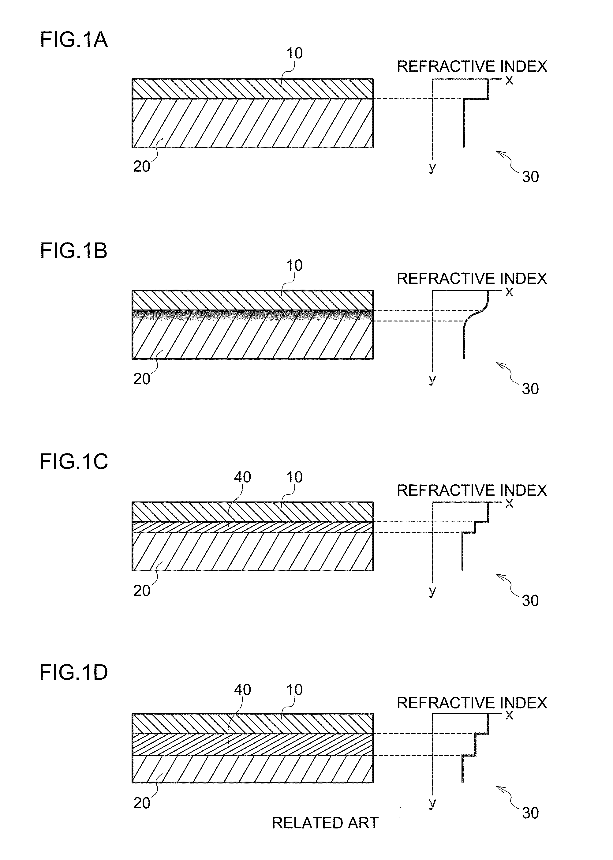
[0010]In view of these circumstances, a first aspect of the present invention aims to provide a method of manufacturing a film with a coating layer capable of significantly weakening reflection between a base material (also referred to as a support or a film) and the coating layer and significantly reducing interference fringe owing to this reflection. In addition, in view of these circumstances, a second aspect of the present invention aims to provide a method of manufacturing a film with a coating layer capable of significantly reducing curing wrinkles.
[0014]In the method of manufacturing a film with a coating layer according to the present invention, it is preferable that the actinic-ray is an ultraviolet light and that at least one of the one or more the photopolymerization initiators have a molar absorption coefficient (molar absorptivity) of 500 (1 / (mol·cm)) or more at UV light wavelength. This enables to enhance a curing efficiency.
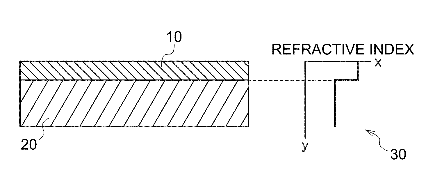
[0016]A film with a coating layer capable of significantly weakening reflection of light from the interface between the coating layer and the support can be manufactured.

Problems solved by technology

This anti-reflection film may be peeled off or damaged when dust, oil, or the like is wiped off from the surface.
However, it has also been known that interference fringe (grease-stain-like rainbow-colored unevenness) occurs when the hard coat layer is provided between the base material and the anti-reflection film, disadvantageously resulting in deterioration in visibility of the display.
This interference fringe has been known to occur due to interference between light reflected from the surface of the hard coat layer and light reflected from an interface between the hard coat layer and the base material.

Method used


Image

  • Method of manufacturing film with a coating layer
  • Method of manufacturing film with a coating layer
  • Method of manufacturing film with a coating layer

Examples


experiment 1

Evaluations

[0054]Next, details of evaluations and evaluation results regarding the method of manufacturing a film with a coating layer according to the present invention are described. Samples for evaluation were manufactured by using an extrusion-type coating apparatus to apply a coating liquid containing an actinic-ray curable resin onto a support under certain conditions to form a coating layer and by irradiating the formed coating layer with an ultraviolet ray (UV). In the evaluations, a UV curable resin was used as an actinic-ray curable resin, and a UV curable monomer was used as an actinic-ray curable monomer.

[0055]Here, the samples were each manufactured with amounts and ratios of the UV curable resin and the UV curable monomer contained in the coating liquid, and irradiance and amount of irradiation of UV irradiation varied. The manufactured samples were evaluated regarding interference fringe and clarity of the interface between the support and the coating layer.

[0056](1) ...

experiment 2

Evaluations

[0090]Details of evaluations and evaluation results regarding the method of manufacturing a film with a coating layer according to the present invention are described. Samples for evaluation were manufactured by using an extrusion-type coating apparatus to apply a coating liquid containing an actinic-ray curable resin onto a support under certain conditions to form a coating layer and by irradiating the formed coating layer with an ultraviolet ray (UV). In the evaluations, a UV curable resin was used as an actinic-ray curable resin, and a UV curable monomer was used as an actinic-ray curable monomer.

[0091]Here, the samples were each manufactured with amounts and ratios of the UV curable resin and the UV curable monomer contained in the coating liquid, and irradiance and amount of UV irradiation varied. The manufactured samples were evaluated regarding interference fringe and clarity of the interface between the support and the coating layer.

[0092](1) Preparation of Suppor...

experiment 3

[0106]Next, details of evaluations regarding a change of curing efficiency according differences in molar absorption efficiency of polymerization initiators are described. This evaluation was performed by using coating liquids in which only the type of polymerization initiators was changed and the others were the same as the experiments 1 and 2.

[0107]The curing efficiency was evaluated as “excellent” when the coating layer was curable with a light quantity (amount of light) of 10 to 20 mJ / cm2 or less, “good” when the coating layer was curable with a light quantity of 20 to 30 mJ / cm2 or less, and “fair” when the coating layer was curable with a light quantity of more than 30 mJ / cm2.

[0108]The absorption coefficient (1 / (mol·cm)) of a light having a wavelength of 365 nm for each polymerization initiator are as below.

[0109]Irgacure 184: 50

[0110]Irgacure 819: 1200

[0111]Irgacure 2959: 0

[0112]Irgacure 369: 3400

[0113]Evaluation results are shown below.

[0114]

TABLE 3ADDITION OFINITIATOR HAVING...


PUM

PropertyMeasurementUnit
wavelengthaaaaaaaaaa
irradianceaaaaaaaaaa
thicknessaaaaaaaaaa

Abstract

A method of manufacturing a film with a coating layer includes a preparing step of preparing a coating liquid containing one or more photopolymerization initiator, a solvent, an actinic-ray curable monomer, and an actinic-ray curable resin, an applying step of applying the coating liquid onto a support to form a coating layer; and a irradiation step of irradiating the coating layer with an actinic ray, wherein in the irradiation step, the coating layer is irradiated with the actinic ray in a state where the coating layer contains the solvent of 10 wt % or more.

Description

BACKGROUND OF THE INVENTION[0001]1. Field of the Invention[0002]The present invention relates to a method of manufacturing a film with a coating layer and, in particular, to a method of manufacturing a film with a coating layer which is formed by applying a coating liquid containing a solvent onto a support.[0003]2. Description of the Related Art[0004]Conventionally, to prevent surface reflection of a lens, a plastic film, or others, an anti-reflection film is provided on a surface thereof. In recent years, the anti-reflection film is provided on a surface of a liquid-crystal display or a plasma display on a viewing side.[0005]This anti-reflection film may be peeled off or damaged when dust, oil, or the like is wiped off from the surface. To address this problem, a hard coat layer having a thickness of several to several tens of micrometers is provided between the anti-reflection film and a surface base material (hereinafter also simply referred to as a base material) on a viewing s...

Claims


Application Information

Patent Timeline
Patent Type & Authority Patents(United States)
IPC IPC(8): C08F2/46C08F2/48G02B1/11C08J7/18B05D7/04B05D7/24G02B1/10G02B1/111G02B1/14
CPCG02B1/111
Inventor KUNIYASU, SATOSHISAIKAWA, TAMOTSU
Owner FUJIFILM CORP
Learn More