
Damping coupler of electronic power steering apparatus

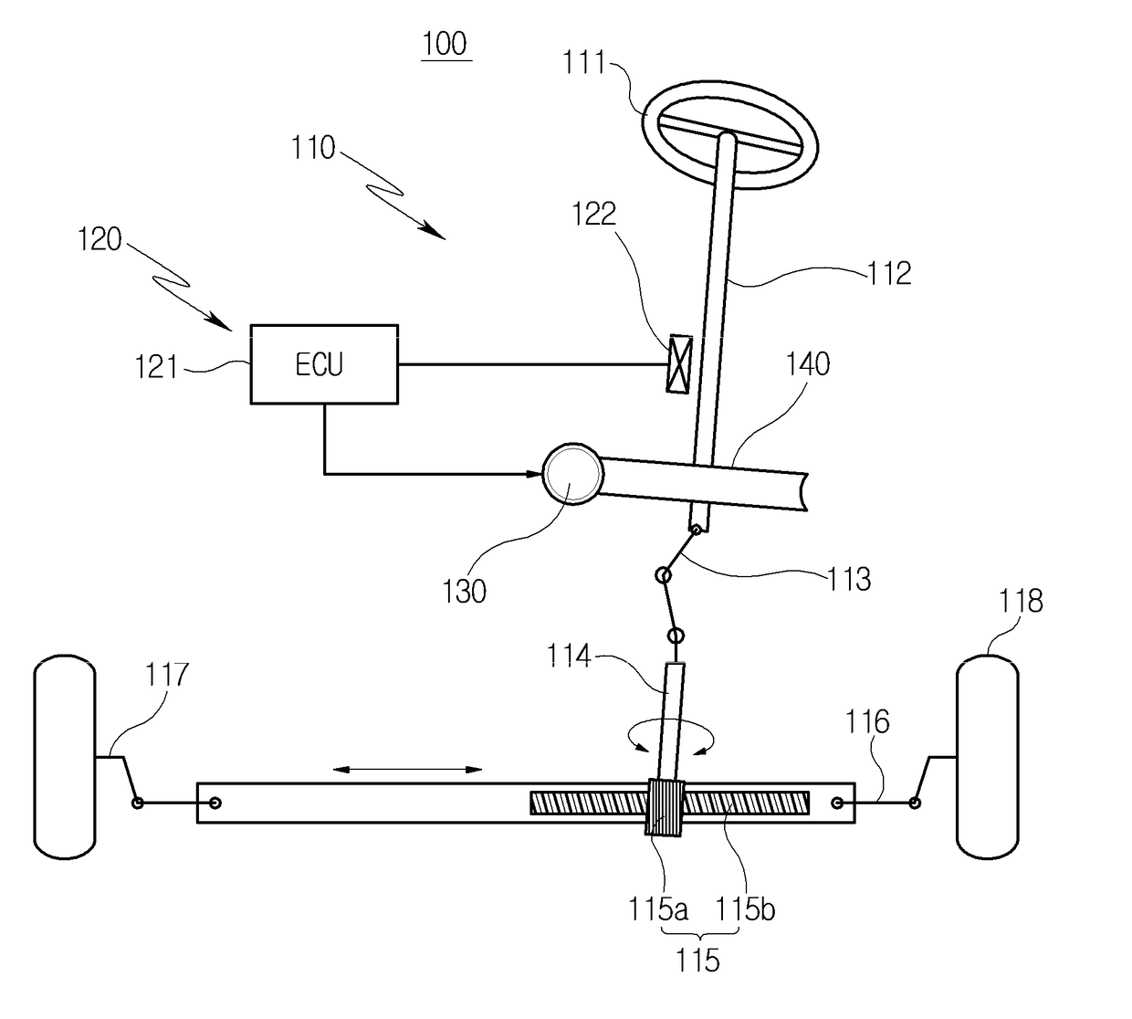
a technology of electronic steering and coupler, which is applied in the direction of couplings, vehicle sub-unit features, transportation and packaging, etc., can solve the problems of large rattle noise made by gaps, and achieve the effect of reducing the rattle nois

Active Publication Date: 2018-03-08
HL MANDO CORP
View PDF4 Cites 3 Cited by
  • Summary
  • Abstract
  • Description
  • Claims
  • Application Information

AI Technical Summary

Benefits of technology

The present invention relates to a damping coupler for an electronic steering apparatus that reduces rubble noise caused by torque load. The damping coupler is divided into two parts, and surfaces with serrations are coupled together to minimize gaps between them. This reduces ralle noise and improves the performance of the steering apparatus.

Problems solved by technology

However, in this case, when a driving force generated from the motor shaft is transmitted from the worm shaft to the damping coupler, great rattle noise may be made by the gaps.

Method used


Image

  • Damping coupler of electronic power steering apparatus
  • Damping coupler of electronic power steering apparatus
  • Damping coupler of electronic power steering apparatus

Examples


first embodiment

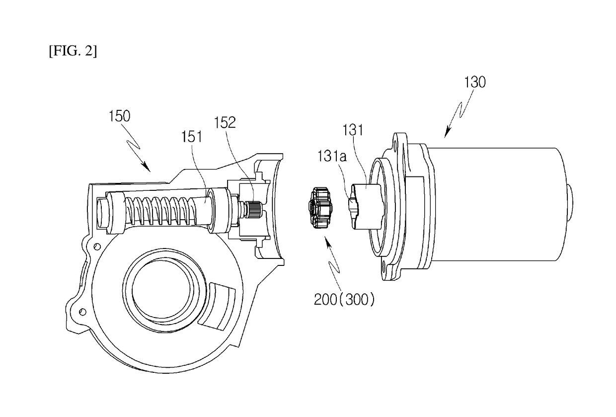
[0048]Referring to FIGS. 3 and 4, the damping coupler 200 of the first embodiment includes a first spline 210, a second spline 220, and a molding 230.

[0049]A first shaft hole 211 is formed in a center of the first spline 210 such that an end of the worm shaft 151 (see FIG. 2) is inserted therein. A plurality of first serrations 212 is axially formed around the first shaft hole 211. The first serrations 212 are coupled to spaces 153 (see FIG. 5) between the serrations formed on an end of the worm shaft. The first spline 210 has a plurality of first protrusions 213 protruding outwards. The first protrusion 213 has a predetermined height in a radial direction from the outer circumference of the first spline 210. Further, the first protrusion 213 may have a predetermined width in an arc direction from the outer circumference of the first spline 210. The plurality of first protrusions 213 may be formed on the outside of the first spline 210 at regular intervals.

[0050]The second spline 22...

second embodiment

[0062]FIG. 6 is an exploded perspective view illustrating a damping coupler according to the present disclosure.

[0063]Referring to FIG. 6, the damping coupler 300 according to the second embodiment includes a first spline 310, a second spline 320, and a molding 330.

[0064]A first shaft hole 311 is formed in a center of the first spline 310 such that the end of the worm shaft 151 (see FIG. 2) is inserted therein. A plurality of first serrations 312 is axially formed around the first shaft hole 311 at regular intervals. The first serrations 312 are coupled to spaces 153 (see FIG. 7) between the serrations formed on the end of the worm shaft. The first spline 310 has a plurality of first protrusions 313 protruding outwards. The first protrusion 313 has a predetermined height in a radial direction from the outer circumference of the first spline 310. Further, the first protrusion 313 may have a predetermined width in an arc direction from the outer circumference of the first spline 310. ...


PUM


Abstract

Disclosed herein is a damping coupler of an electronic steering apparatus. The damping coupler includes a first spline having a first shaft hole such that a worm shaft is inserted therein, with a first serration being formed in the first shaft hole to engage with a serration of the worm shaft; a second spline coupled to a side of the first spline, and having a second shaft hole such that the worm shaft is inserted therein, with a second serration being formed in the second shaft hole to engage with a serration of the worm shaft; and a molding surrounding outsides of the first and second splines, and coupled to a motor shaft.

Description

CROSS-REFERENCE TO RELATED APPLICATION[0001]This application claims priority to Korean Patent Application No. 10-2016-0114417, filed on Sep. 6, 2016, the disclosure of which is incorporated herein by reference in its entirety.BACKGROUND OF THE INVENTIONField of the Invention[0002]Exemplary embodiments of the present disclosure relate to an electronic steering apparatus, and more particularly, to a damping coupler of an electronic steering apparatus.Description of the Related Art[0003]A steering apparatus of a vehicle is an apparatus that freely change a moving direction of the vehicle by turning a steering wheel and aids in moving the vehicle in a desired direction by optionally changing a rotation center around which a wheel of the vehicle rotates. As an auxiliary power mechanism that is configured so that it is easier for a driver to steer a vehicle, a power steering apparatus is utilized. Such a power steering apparatus mainly includes a hydraulic steering apparatus that uses hyd...

Claims


Application Information

Patent Timeline
IPC IPC(8): B62D5/04
CPCB62D5/0403B60Y2306/09B62D7/226B62D5/0454B62D3/04B62D5/04F16D3/06F16H57/0006B62D5/0409F16D3/54F16D3/68F16D1/0805F16D1/0829
Inventor YUN, TAE JUNG
Owner HL MANDO CORP
Learn More