
Electro-optic phase modulator with no residual amplitude modulation

a phase modulator and optical phase technology, applied in electromagnetic wave modulation, instruments, electrical equipment, etc., can solve problems such as system damag

Active Publication Date: 2018-03-01
IBM CORP
View PDF0 Cites 20 Cited by
  • Summary
  • Abstract
  • Description
  • Claims
  • Application Information

AI Technical Summary

Benefits of technology

The patent text is submitted to allow the reader to quickly understand the nature of the invention. It is not meant to constrain the claims or the scope of the invention. The text explains that various features are grouped together in different embodiments to make the disclosure easier to read. This method of disclosure does not suggest that all features are present in each claim. Inventive subject matter is primarily described in the claims, which are each individually claimed as separate subject matter. The patent text aims to make it easier for R&D personnel to understand the invention without adding additional information.

Problems solved by technology

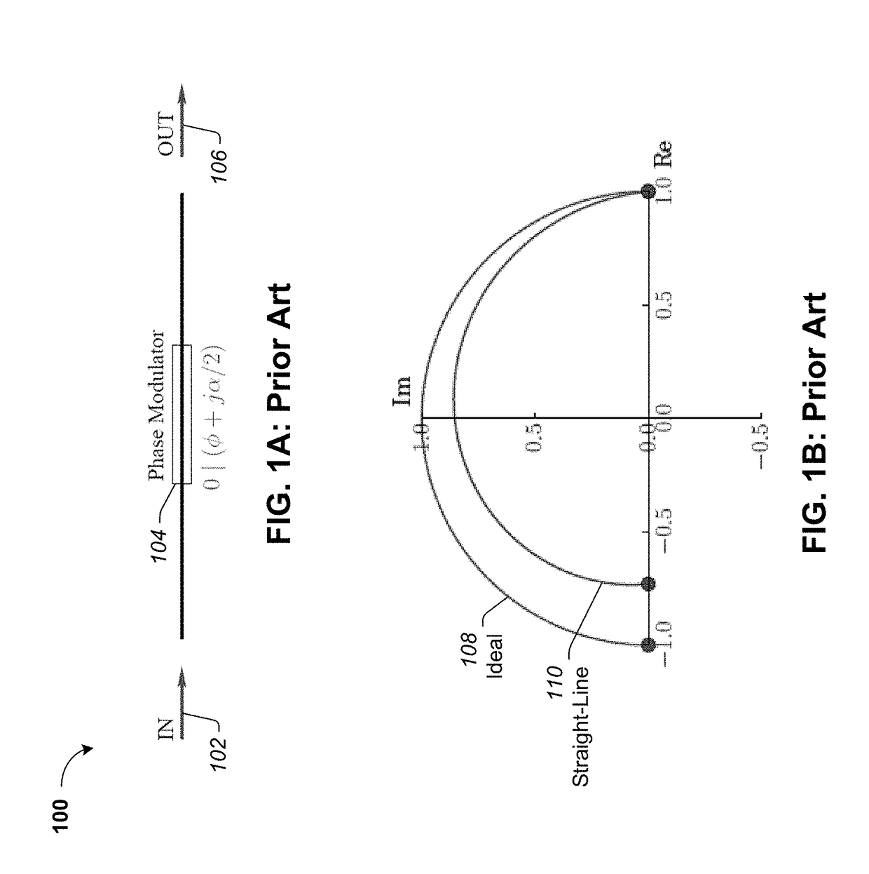
It is generally desirable to provide pure phase modulation without any residual amplitude modulation, which could be detrimental to the system.
The residual amplitude modulation of phase modulators is a salient issue for several applications including, without limitation, optical isolators, optical switches, and advanced imaging techniques such as optical coherence tomography.

Method used


Image

  • Electro-optic phase modulator with no residual amplitude modulation
  • Electro-optic phase modulator with no residual amplitude modulation
  • Electro-optic phase modulator with no residual amplitude modulation

Examples


example process

[0102]With the foregoing overview of various MZPM architectures and configurations, it may be helpful now to consider a high-level discussion of an example process. To that end, FIG. 8 presents an illustrative process 800 for providing optical phase modulation while maintaining an amplitude that is independent of changes in loss introduced by the phase modulator.

[0103]Process 800 is illustrated as a collection of blocks in a logical flow that represents a sequence of operations that can be implemented in hardware, software, or a combination thereof. In the context of software, the blocks represent computer-executable instructions that, when executed by one or more processors, perform the recited operations. Generally, computer-executable instructions may include routines, programs, objects, components, data structures, and the like that perform particular functions or implement particular abstract data types. The order in which the operations are described is not intended to be cons...


PUM


Abstract

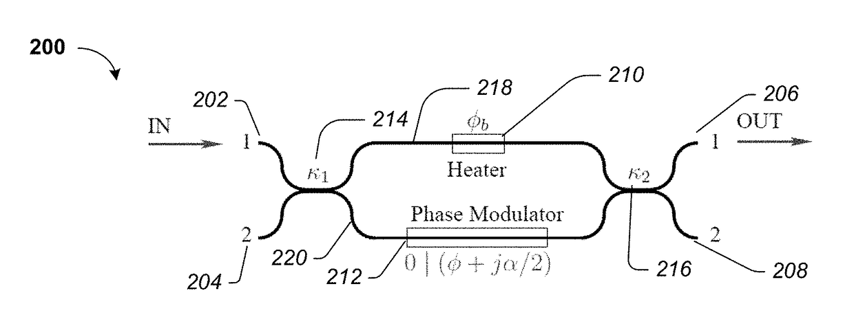
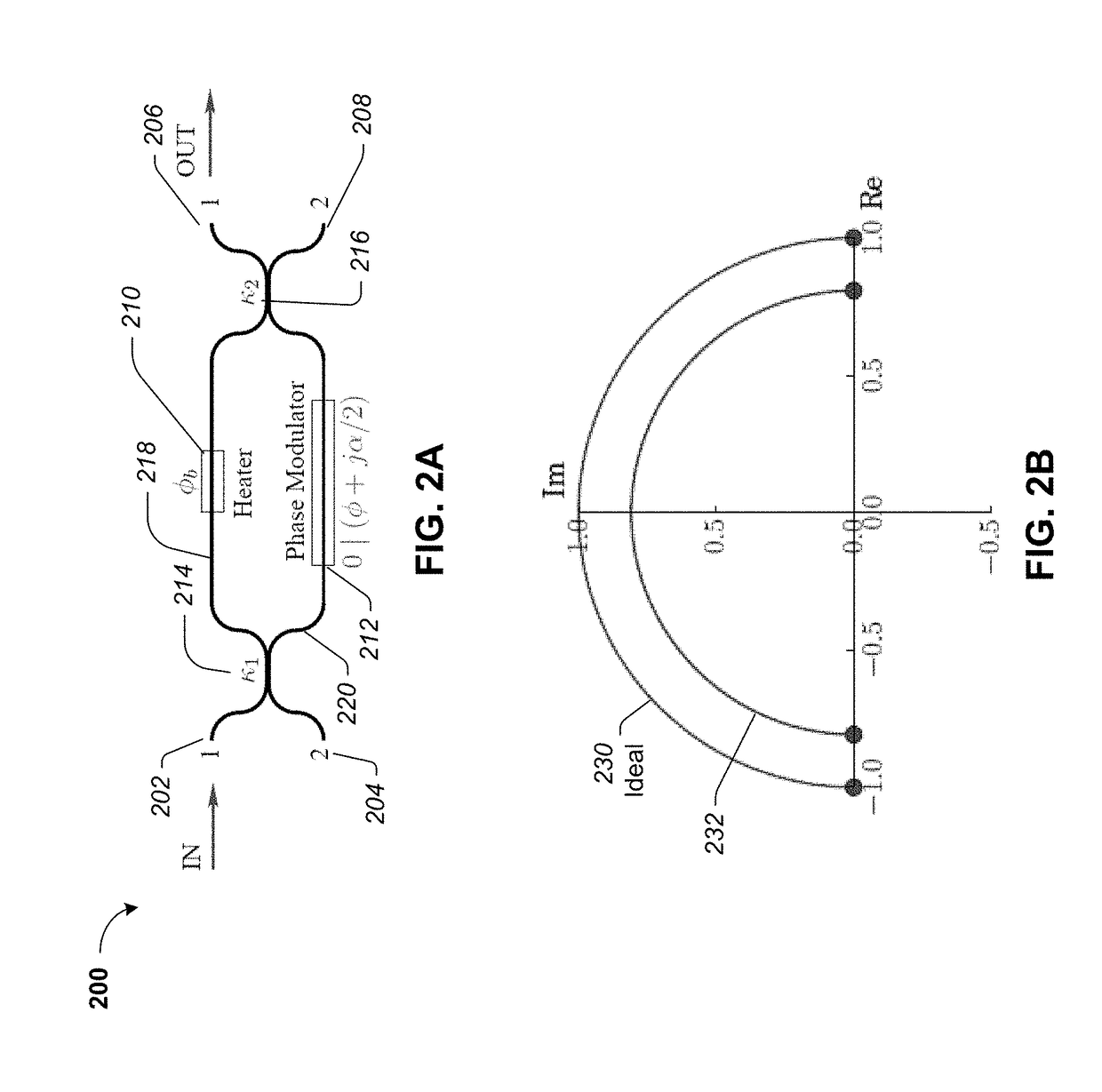
An optical phase modulator includes an input source that is configured to receive a light source. There is an output operative to provide a phase modulated output signal based on the received light source. There is a first optical coupler configured to split the light source into a first optical path of a Mach Zehnder Interferometer (MZI) and a second optical path of the MZI. A static phase shifter is configured to provide a static phase shift to the first optical path. There is a phase modulator in the second optical path. There is a second optical coupler configured to combine the first optical path and the second optical path. The first and second optical couplers are tuned such that the phase modulated optical signal at the output provides a substantially constant amplitude that is independent of a change in loss introduced by the phase modulator.

Description

BACKGROUNDTechnical Field[0001]The present application generally relates to optical modulators to control light signals, and more particularly, to optical phase modulators with controlled residual amplitude modulation.Description of the Related Art[0002]An electro-optic modulator is an optoelectronic device where a signal-controlled element having an electro-optic effect is used to modulate a beam of light. The modulation may be with respect to the phase, frequency, amplitude, or polarization of the beam of light. Electro-optic phase modulators are largely used in fiber optical communication systems for realizing high-speed phase modulation of optical signals. Various technologies and material platforms can be used to realize a phase modulator. The structure generally includes an optical waveguide that has a refractive index that is modulated by applying an RF electrical field that spatially overlaps with an optical mode of the waveguide.[0003]After propagating through an L-long pha...

Claims


Application Information

Patent Timeline
Patent Type & Authority Applications(United States)
IPC IPC(8): H04B10/548H03C7/00
CPCH03C7/00H04B10/548G02F1/0123G02F1/225G02F2201/16
Inventor DUPUIS, NICOLASLEE, BENJAMIN G.TAUBENBLATT, MARC A.
Owner IBM CORP
Learn More