
Camera mounting

a technology for mounting cameras and cameras, applied in the field of video camera mounting, can solve problems such as body loosening from the bas

Inactive Publication Date: 2018-03-01
TOMTOM INT BV
View PDF7 Cites 11 Cited by
  • Summary
  • Abstract
  • Description
  • Claims
  • Application Information

AI Technical Summary

Benefits of technology

The patent is about a mount that allows for easy swapping of different cameras on an object, like a helmet. The mount has a removable base and a rotatable body that can be adjusted in two ways to have different orientations. A seal helps keep the mount secure even when the body is rotated. The interlocking arrangement between the toothed disc and the set of teeth makes the mount compact. The mounting portion can be pivoted from a lowered position in the horizontal plane of the body. The technical effects of the patent are improved flexibility and adjustability for cameras on an object, while keeping the mount low in profile.

Problems solved by technology

However a potential problem with a frictional engagement is that the body may be loosened from the base during use of the mount, especially if the mount is not generally stationary but subject to forces during wear.

Method used


Image

  • Camera mounting
  • Camera mounting
  • Camera mounting

Examples


Embodiment Construction

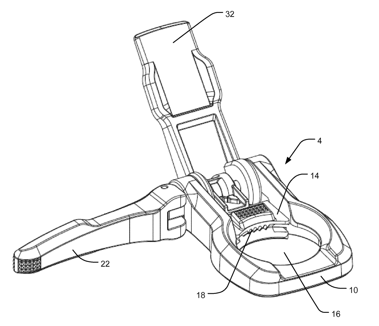
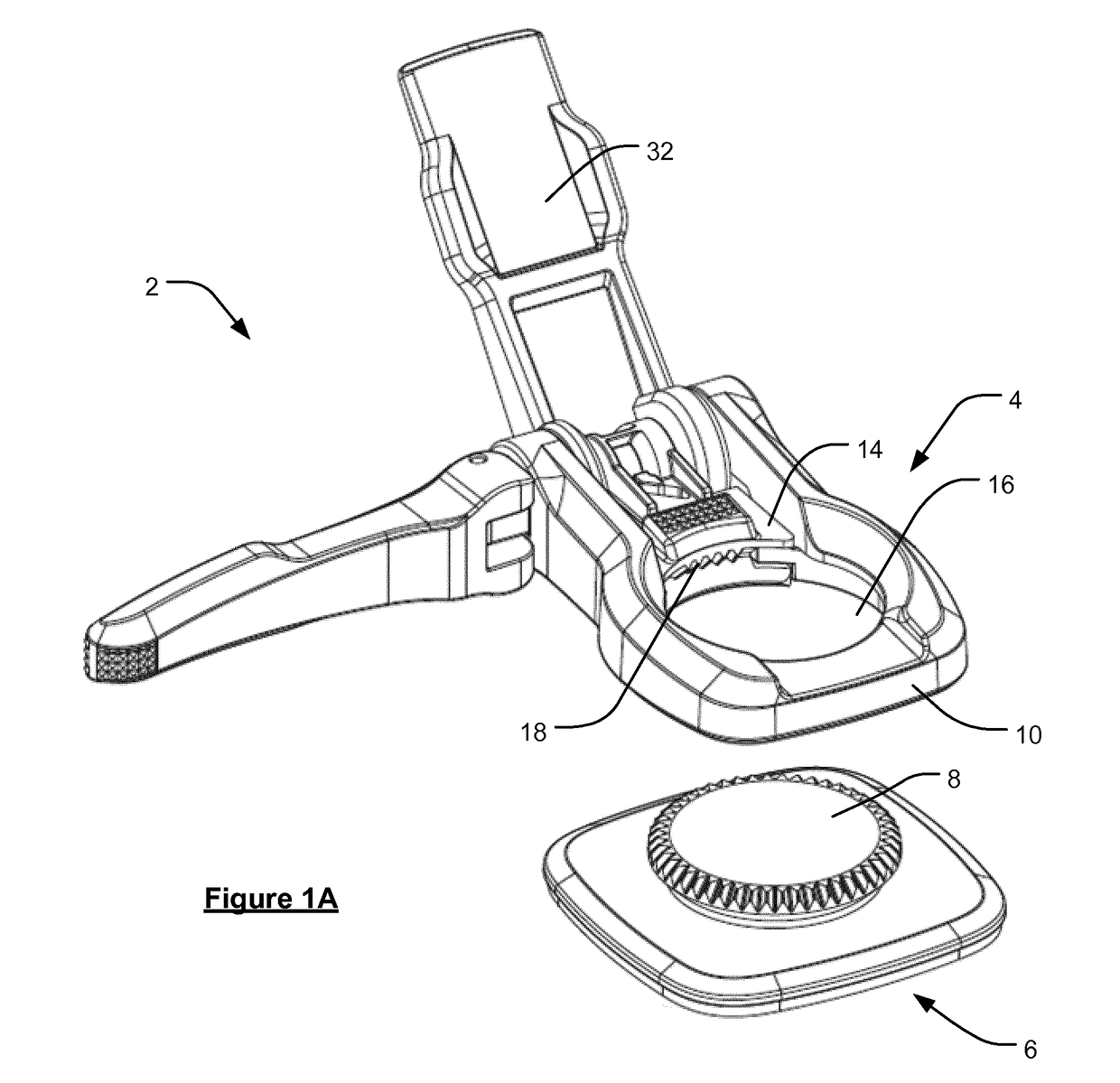
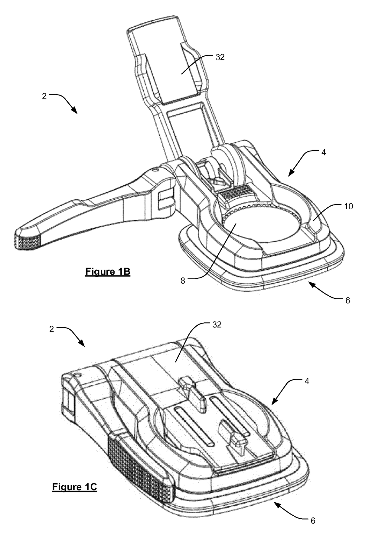
[0026]There is generally seen in FIGS. 1A to 1C a camera mount 2 comprising a mount body 4 removably connected to a mount base 6. It will be appreciated that one or more such mount bodies 4 may be interchanged for a given base 6. The mount base 6 may, for example, be fixed to an object such as a helmet by adhesive. Both the mount body 4 and mount base 6 are made of a hard plastics material.

[0027]In FIG. 1A it can be seen that the mount base 6 takes the form of a generally flat plate with a toothed disc 8 upstanding on its upper surface. The lower surface of the base 6 may be flat or slightly curved. The mount base 6 defines a horizontal plane for the mount 2, in other words, a plane from which the orientation of the camera on the mount 2 may be adjusted. The toothed disc 8 provides a dual function. Firstly, it forms a removable connection with the mount body 4. Secondly, it enables the mount body 4 to be controllably rotated about a vertical axis passing through the base 6. This is ...


PUM


Abstract

An adjustable mount (2) for a camera, comprising a base (6) for mounting to an object in a fixed position and a body (4) that is removably connected to the base (6), the base (6) defining a horizontal plane for the adjustable mount (2), and wherein, when the body (4) is connected to the base (6) in use, the body (4) is rotatable about a vertical axis passing through the base (6) and a mounting portion (32) of the body (4) is pivotable away from the horizontal plane so as to enable adjustment of an orientation of a camera supported on the mounting portion (32).

Description

FIELD OF THE INVENTION[0001]This invention relates to the mounting of cameras, including still cameras and particularly video cameras. Illustrative embodiments of the invention relate to mounts for video cameras for use during outdoor activities and action sports e.g. cycling, mountain biking, hiking, climbing, skiing and snowboarding, surfing, sky diving, sub-aqua diving, etc.BACKGROUND OF THE INVENTION[0002]It is known to mount still and video cameras so that they can record images or video during action sports, for example wearable video cameras can be mounted to a helmet, bicycle, surf board, etc. to capture action footage. So-called “action cams” can typically be mounted in different orientations, e.g. on a helmet, but the orientation of the camera is generally fixed once it has been mounted in a particular position. This can be problematic when activities do not take place on the level and the camera may be tilted or inverted during use. A horizon adjustment may be required to...

Claims


Application Information

Patent Timeline
IPC IPC(8): G03B17/56F16M13/02
CPCF16M13/022F16B1/00F16B47/00F16M11/14A45F5/02A45F2003/006A45F2005/025A45F2200/0533F16B2001/0035A45F3/14F16M11/041G03B17/561G03B17/00G03B17/56F16B2200/83
Inventor TAYLOR, CHRISTOPHER JAMESRIDDIFORD, MARTIN
Owner TOMTOM INT BV
Learn More