Eureka AIR delivers breakthrough ideas for toughest innovation challenges, trusted by R&D personnel around the world.

Optical system

a technology of optical system and lens, applied in the field of optical system, can solve the problems of adverse effects on the focus speed and accuracy of the lenses (which can move, etc.), and achieve the effect of improving the focus speed and accuracy of the lenses and reducing magnetic interferen

Active Publication Date: 2018-03-01
TDK TAIWAN
View PDF8 Cites 11 Cited by
  • Summary
  • Abstract
  • Description
  • Claims
  • Application Information

AI Technical Summary

Benefits of technology

The invention is about a dual-lens camera system that reduces the interference between the magnetic elements of the two lens driving modules. This improves the speed and accuracy of focusing on the lenses in the system.

Problems solved by technology

In existing dual-lens camera systems, two lens driving modules are usually arranged close to each other, and as a result, magnetic interference between the magnets of the two lens driving modules is likely to occur, causing the focus speed and accuracy of the lenses (which can move with the movement of the movable parts in the lens driving modules) to be adversely affected.

Method used

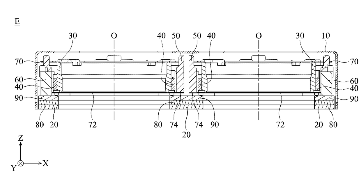
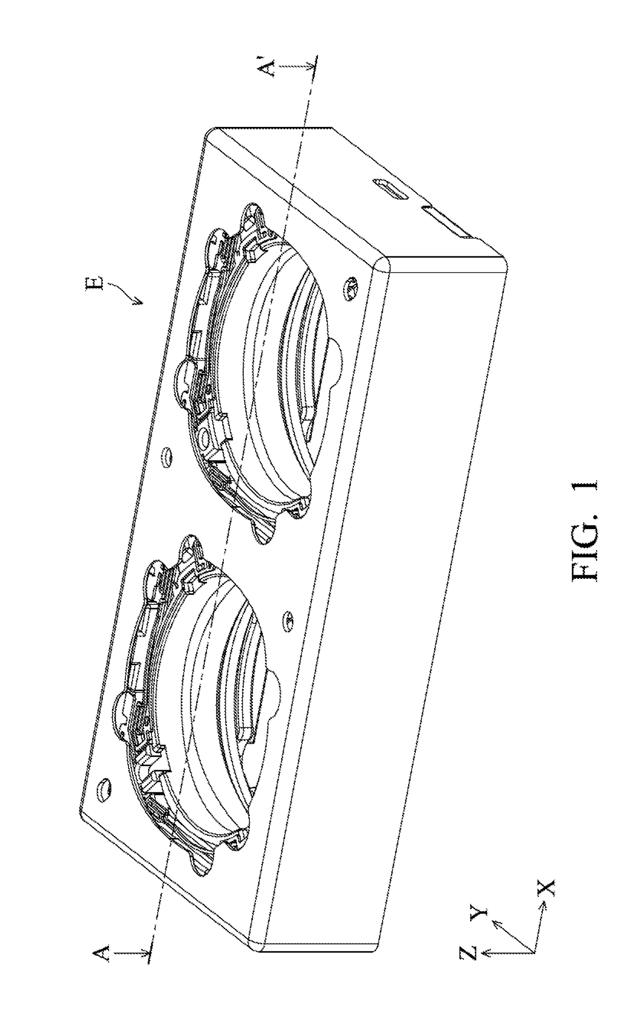

Image

  • Optical system
  • Optical system
  • Optical system

Examples


Embodiment Construction

[0019]The making and using of the embodiments of a dual-lens camera system are discussed in detail below. It should be appreciated, however, that the embodiments provide many applicable inventive concepts that can be embodied in a wide variety of specific contexts. The specific embodiments discussed are merely illustrative of specific ways to make and use the embodiments, and do not limit the scope of the disclosure.

[0020]Unless defined otherwise, all technical and scientific terms used herein have the same meaning as commonly understood by one of ordinary skill in the art to which this invention belongs. It should be appreciated that each term, which is defined in a commonly used dictionary, should be interpreted as having a meaning conforming to the relative skills and the background or the context of the present disclosure, and should not be interpreted in an idealized or overly formal manner unless defined otherwise.

[0021]Referring to FIGS. 1 to 3, wherein FIG. 1 is a schematic ...


PUM


Abstract

An optical system is provided, including a base, a first lens driving module and a second lens driving module. The first lens driving module includes a first holder, a first magnet, and a first coil corresponding to the first magnet, wherein the first holder is used to hold a first optical element and has a first side. The second lens driving module includes a second holder, a second magnet, and a second coil corresponding to the second magnet, wherein the second holder is used to hold a second optical element and has a second side. The first side is adjacent and parallel to the second side, and no magnet is disposed on the first side or second side.

Description

CROSS-REFERENCE TO RELATED APPLICATIONS[0001]The present application claims priority to U.S. Provisional Patent Application No. 62 / 378,842, filed on Aug. 24, 2016, and China Patent Application No. 201710507249.5 filed on Jun. 28, 2017, which is incorporated by reference herein in its entirety.BACKGROUND OF THE INVENTIONField of the Invention[0002]The invention relates to an optical system, such as a duel-lens camera system, and more particularly to a dual-lens camera system that can move lenses using an electromagnetic force.Description of the Related Art[0003]In existing dual-lens camera systems, two lens driving modules are usually arranged close to each other, and as a result, magnetic interference between the magnets of the two lens driving modules is likely to occur, causing the focus speed and accuracy of the lenses (which can move with the movement of the movable parts in the lens driving modules) to be adversely affected. Therefore, what is needed is a dual-lens camera syste...

Claims


Application Information

Patent Timeline
Patent Type & Authority Applications(United States)
IPC IPC(8): G02B7/02G02B7/04G03B13/36
CPCG02B7/021G03B13/36G02B7/04G02B7/06G02B7/09G03B3/10G03B19/14G03B19/22G03B2205/0007G03B2205/0069G02B7/08
Inventor WU, FU-YUANKAO, KUO-CHUNSONG, SIN-JHONG
Owner TDK TAIWAN
Why Eureka
Eureka Blog
Learn More