
Motor control device, motor control method and computer readable recording medium

a technology of motor control and control method, which is applied in the direction of electric controller, program control, electric programme control, etc., can solve the problem of low frequency vibration under servo control bandwidth

Active Publication Date: 2018-02-22
FANUC LTD
View PDF3 Cites 3 Cited by
  • Summary
  • Abstract
  • Description
  • Claims
  • Application Information

AI Technical Summary

Benefits of technology

The present invention provides a motor control device, method, and computer-readable recording medium that can adjust compensation torque based on changes in operating conditions, such as cutting feed and rapid traverse, and the velocity controller's gain. The compensation torque calculation unit can decrease the compensation gain when the velocity controller's gain changes in response to the operating condition. This allows for efficient and effective control of the motor's movement.

Problems solved by technology

There are cases where the velocity of a driven part of a machine and the velocity of the motor do not match due to this spring coupling, whereby a low-frequency vibration under a servo control bandwidth occurs.

Method used


Image

  • Motor control device, motor control method and computer readable recording medium
  • Motor control device, motor control method and computer readable recording medium
  • Motor control device, motor control method and computer readable recording medium

Examples


Embodiment Construction

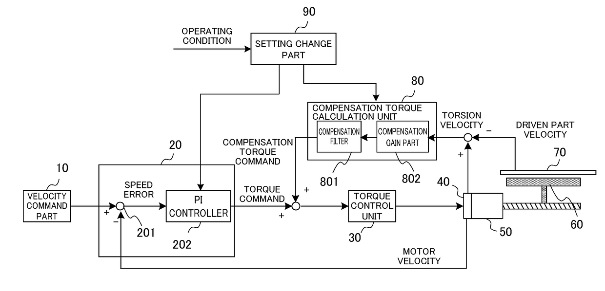
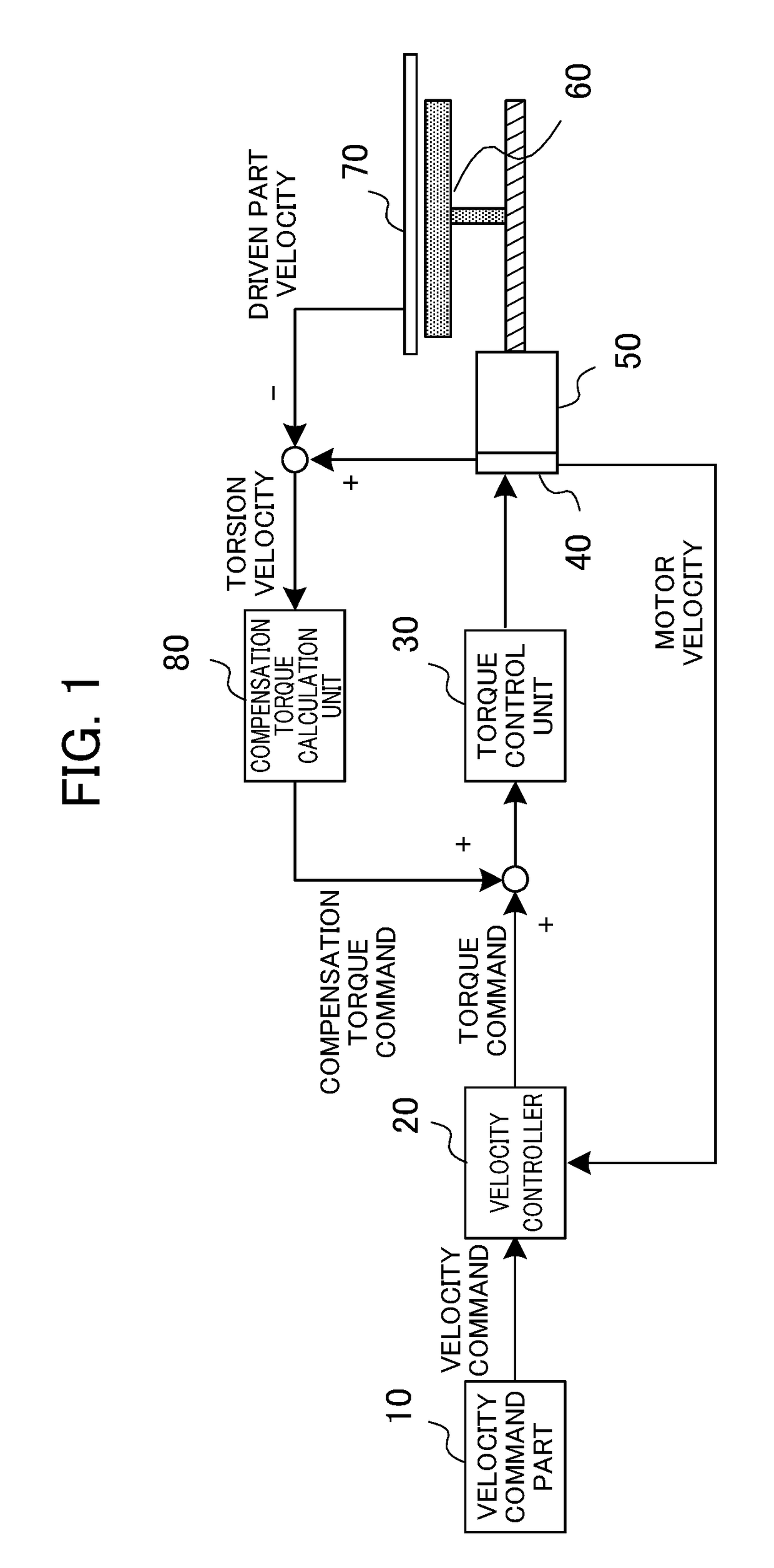
[0026]Hereinafter, embodiments of the present invention will be explained in detail using the drawings. Prior to explanation of the embodiment of the present invention, the technology serving as the premise will be explained. FIG. 1 is a block diagram for explaining the configuration of a motor control device serving as a technical premise. As shown in FIG. 1, a velocity command outputted from a velocity command unit 10 is inputted to a velocity controller 20, and the velocity controller 20 generates a torque command using the inputted velocity command and the inputted motor velocity of a motor 50 (revolution velocity of motor), then outputs the torque command to a torque control unit 30. The torque control unit 30 controls the revolution of the motor 50 based on the addition value of the torque command and a compensation torque command from a compensation torque calculation unit 80. The revolution velocity of the motor 50 is detected by a velocity detector 40 such as an encoder, an...


PUM


Abstract

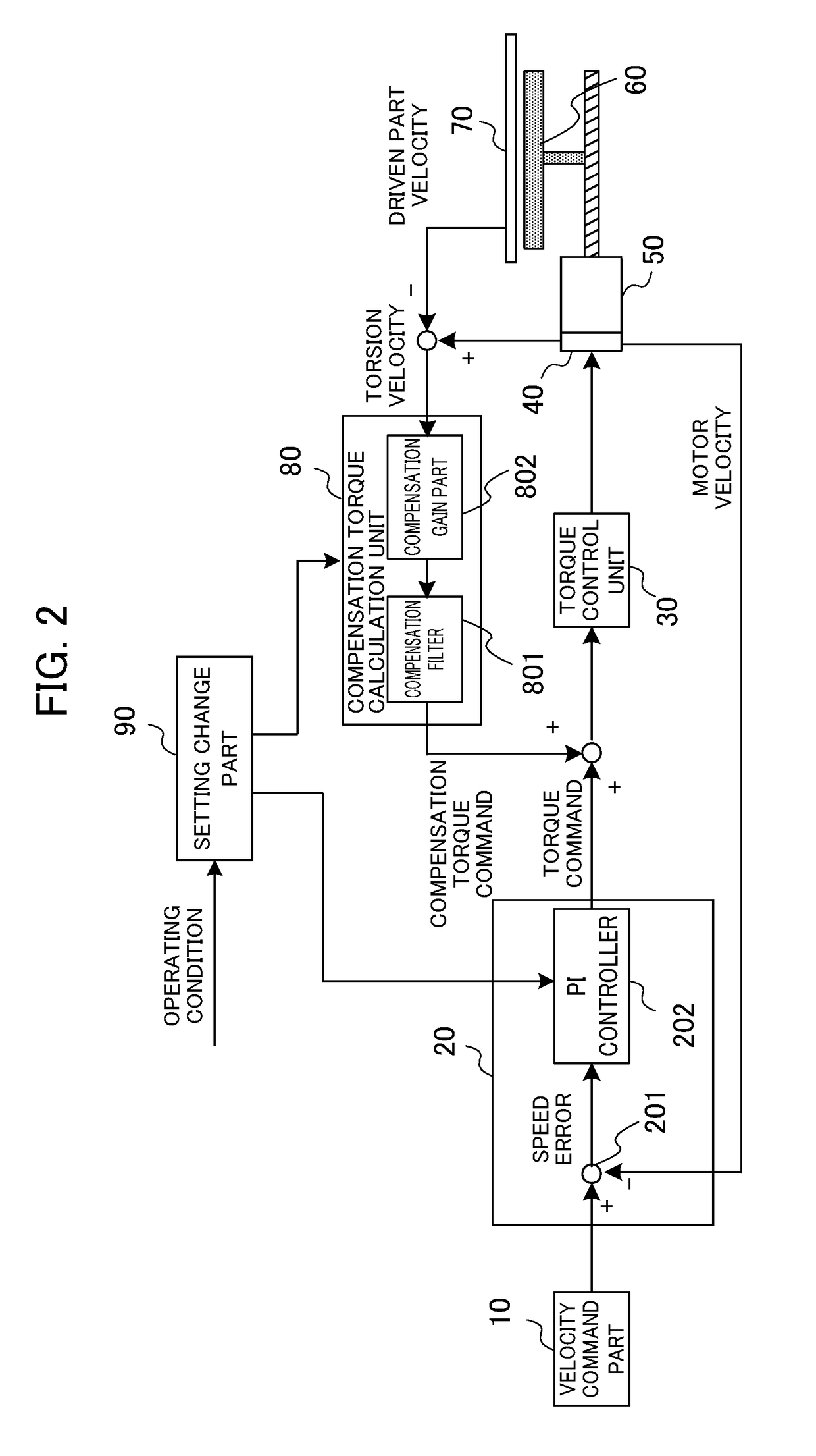
A motor control device includes a velocity controller configured to calculate a torque command from a velocity command and a motor velocity; a compensation torque calculation unit configured to calculate a compensation torque command by multiplying an error between the motor velocity and a velocity of a driven part by a compensation gain and a compensation filter; a torque control unit configured to control torque of a motor based on a value obtained by adding the torque command and the compensation torque command; and a setting change part configured to change a gain of the velocity controller according to an operating condition of the motor control device, and change at least one of the compensation gain and the compensation filter in accordance with a change in the gain of the velocity controller.

Description

[0001]This application is based on and claims the benefit of priority from Japanese Patent Application No. 2016-162096, filed on 22 Aug. 2016, the content of which is incorporated herein by reference.BACKGROUND OF THE INVENTIONField of the Invention[0002]The present invention relates to a motor control device, a motor control method and a computer readable recording medium, and in particular, relates to a motor control device that controls a motor connected with a driven part via an elastically deformable element, a motor control method and a computer readable recording medium.Related Art[0003]A machine tools, industrial machine, etc. have feed axes to drive driven part such as tables or rotary tables by servo motors via mechanical parts such as ball screws, couplings, or reducers. A machine which uses elastic parts such as flexible coupling or reducers tends to have low-frequency vibration and, in that case, the feed axis can be regarded as spring coupled state. There are cases whe...

Claims


Application Information

Patent Timeline
Patent Type & Authority Applications(United States)
IPC IPC(8): G05B19/416G05B19/19G05B11/01
CPCG05B19/4163G05B19/19G05B2219/41G05B2219/43117G05B11/011H02P6/06H02P6/08H02P23/14
Inventor NAKAMURA, TSUTOMUIKAI, SATOSHI
Owner FANUC LTD
Learn More