
On-Line Signal Event Detection and Identification Method and Apparatus

a technology of applied in the field of online signal event detection and identification method and apparatus, can solve the problems of increasing cost, compromising system portability, and inability to achieve adequate detection and identification, so as to achieve accurate detection and identification of the underlying signal, increase hardware resources, and increase cost

Inactive Publication Date: 2018-02-15
MAGIEROWSKI SEBASTIAN +1
View PDF5 Cites 4 Cited by
  • Summary
  • Abstract
  • Description
  • Claims
  • Application Information

AI Technical Summary

Benefits of technology

The patent text discusses a method for accurately detecting and identifying signals in real-time communication and measurement systems. The method uses off-line methods that store a significant portion of the signal stream to provide global statistics and apply anti-causal methods for recovery of the underlying message. However, these off-line methods have limitations such as requiring significant parts of the signal stream to be captured before processing and increased hardware requirements. The technical effect of the patent is to provide a solution for accurate detection and identification of signals in real-time systems without the limitations of off-line methods.

Problems solved by technology

The achievement of adequate detection and identification is complicated by the fact that the original source signal is compromised by noise and distortion during the message transmission process through its respective channel.
However off-line methods are not appropriate for real-time communication and measurement systems.
Further, the memory requirements of off-line methods call for greater hardware resources therefore increasing cost and compromising the portability of the system as subject to size and energy needs.
These methods are not applicable to communication or measured systems with compromised synchrony or asynchronous systems that abandon clocking methods altogether.
In the art, this method is capable of detecting a change, but, alone, does not identifying the value of the new level.
Should these assumptions not be appropriate for the incoming signal a substantial degradation in the accuracy of the method can be observed.

Method used


Image

  • On-Line Signal Event Detection and Identification Method and Apparatus
  • On-Line Signal Event Detection and Identification Method and Apparatus
  • On-Line Signal Event Detection and Identification Method and Apparatus

Examples


Embodiment Construction

[0047]Following below are more detailed descriptions of various concepts related to, and embodiments of, inventive methods and apparatus for on-line high-speed signal event detection and identification. It should be appreciated that various concepts introduced above and detailed below may be implemented in any of a number of ways as the disclosed concepts are not limited to any particular manner of implementation.

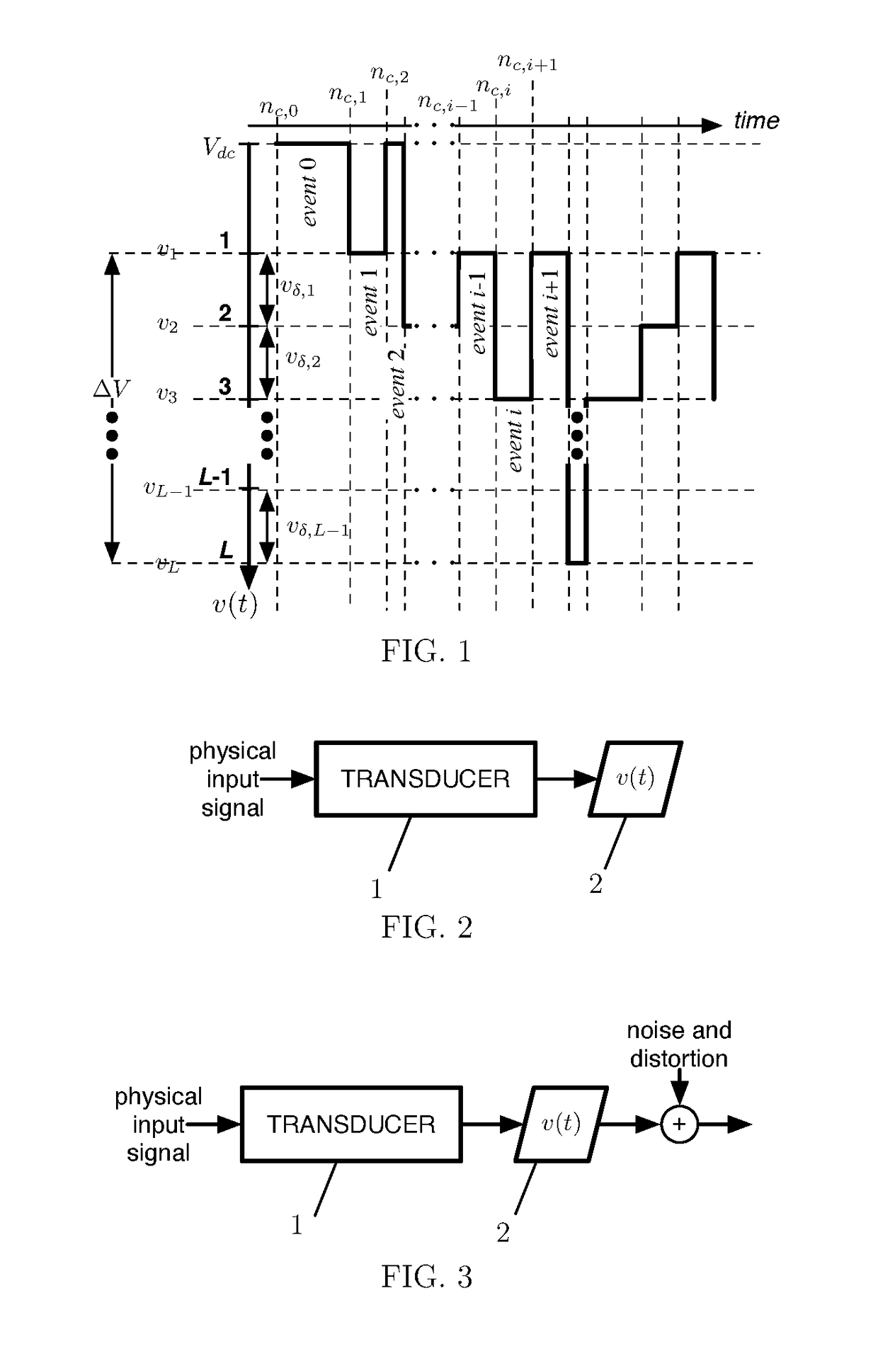
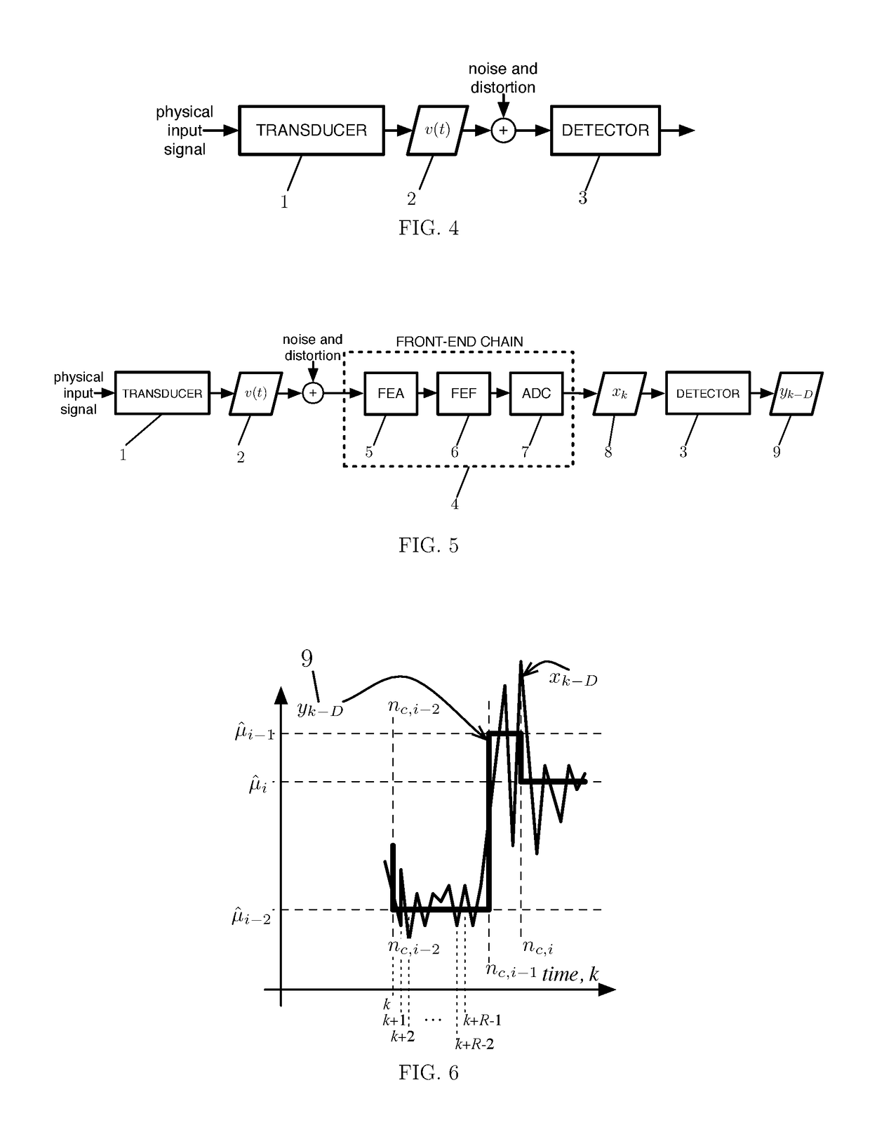
[0048]FIG. 5 illustrates, in an exemplary context not meant to be limiting, a more detailed signal reception scheme of the detector [3], the unit responsible for the online detection and identification of high-speed signals. The exemplary arrangement shown comprises of a transducer [1] and front-end chain [4]. This arrangement is just one possible configuration of a detector [3] within a system intended to process external signals and is not meant to be limiting. For example, the front-end chain [4] may be entirely dispensed with and the detector [3] attached directly to th...


PUM


Abstract

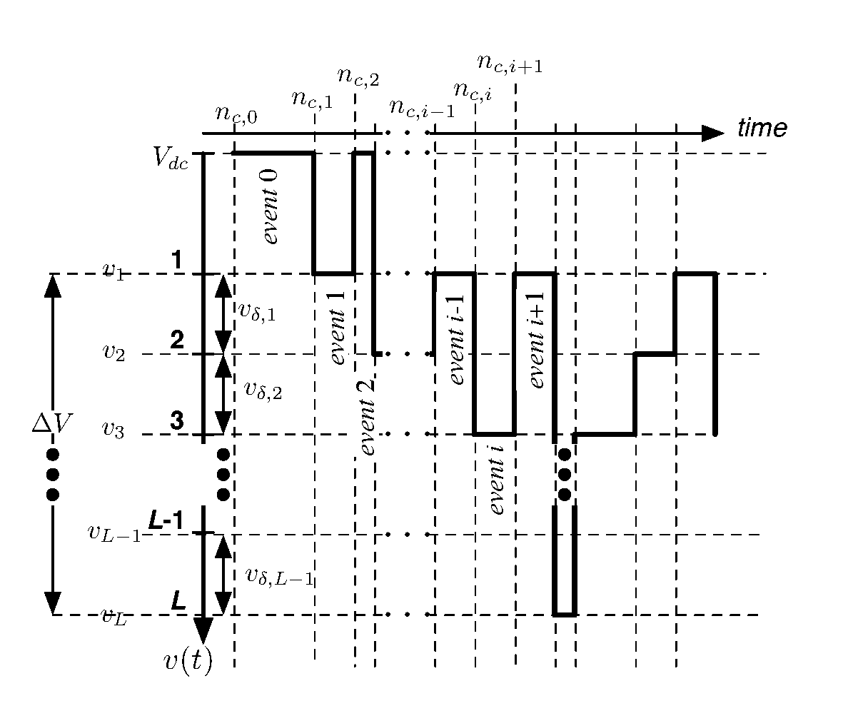
A method of and apparatus for on-line detection and identification of synchronous and asynchronous piecewise-constant signals corrupted by noise and distortion. The method achieves joint temporal and amplitude detection and identification by following an initial amplitude approximation with a change detection that continually converges to an accurate joint identification while continually correcting intermediate approximation errors via analysis of temporal signatures. In turn, the temporal identifications employ accumulated statistics partly determined by the initial amplitude approximation.

Description

CROSS-REFERENCE TO RELATED APPLICATIONS[0001]This application claims the benefit of provisional patent application Ser. No. 60 / 204,441, filed 2015 Aug. 13 by the present inventors.BACKGROUND PRIOR ART[0002]The following is a tabulation of some prior art that presently appears relevant:Nonpatent Literature Documents[0003]C. Plesa, C. Dekker, “Data analysis methods for solid-state nanopores,”Nanotechnology, 26 (2015).[0004]E. S. Page, “Continuous inspection schemes,”Biometrika, 41 (1954), pp. 100-115.[0005]C. Raillon, P. Granjon, M. Graf, L. J. Steinbock, A. Radenovic, “Fast and automatic processing of multi-level events in nanopore translocation experiments”, Nanoscale, 4 (2012), pp. 4916-4924.[0006]D. O. North, “An analysis of the factors which determine signal / noise discrimination in pulsed-carrier systems,”Proc. of the IEEE, 51 (1963), pp. 1016-1027.[0007]Many human-made signals and many naturally occurring signals assume a form that can be described as a piecewise-constant signal...

Claims


Application Information

Patent Timeline
Patent Type & Authority Applications(United States)
IPC IPC(8): H04L25/03
CPCH04L25/03834H04L25/03012H04L25/061
Inventor MAGIEROWSKI, SEBASTIANHUANG, YIYUN
Owner MAGIEROWSKI SEBASTIAN
Learn More