Ultrasonic Sealing Apparatus For Use In Bag Filling And Packaging Machine
a sealing apparatus and ultrasonic technology, applied in the field of ultrasonic sealing apparatus, can solve the problems of unfavorable bag mouth folding, and damage to the apparatus, so as to prevent the operation of “idle sealing” and prevent the damage of the ultrasonic sealing apparatus. , to prevent the effect of displacement or folding of the bag mouth
- Summary
- Abstract
- Description
- Claims
- Application Information
AI Technical Summary
Benefits of technology
Problems solved by technology
Method used
Image

Examples
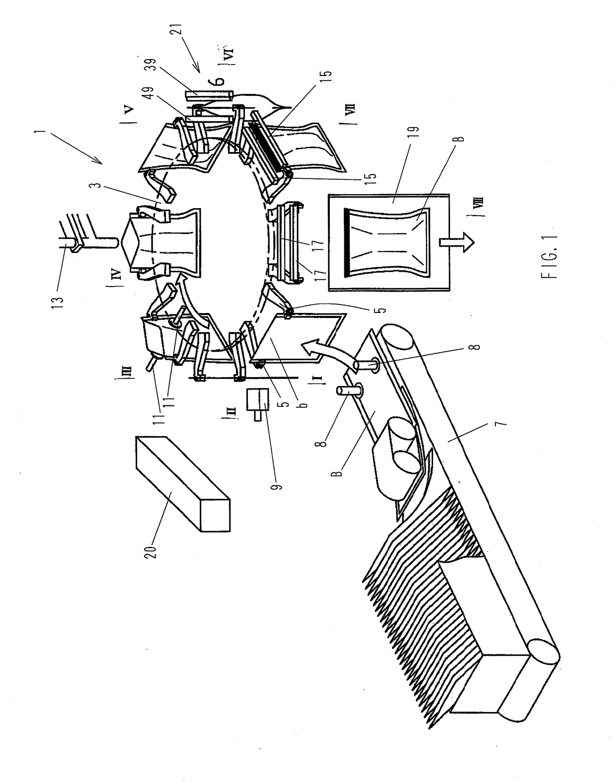
first embodiment
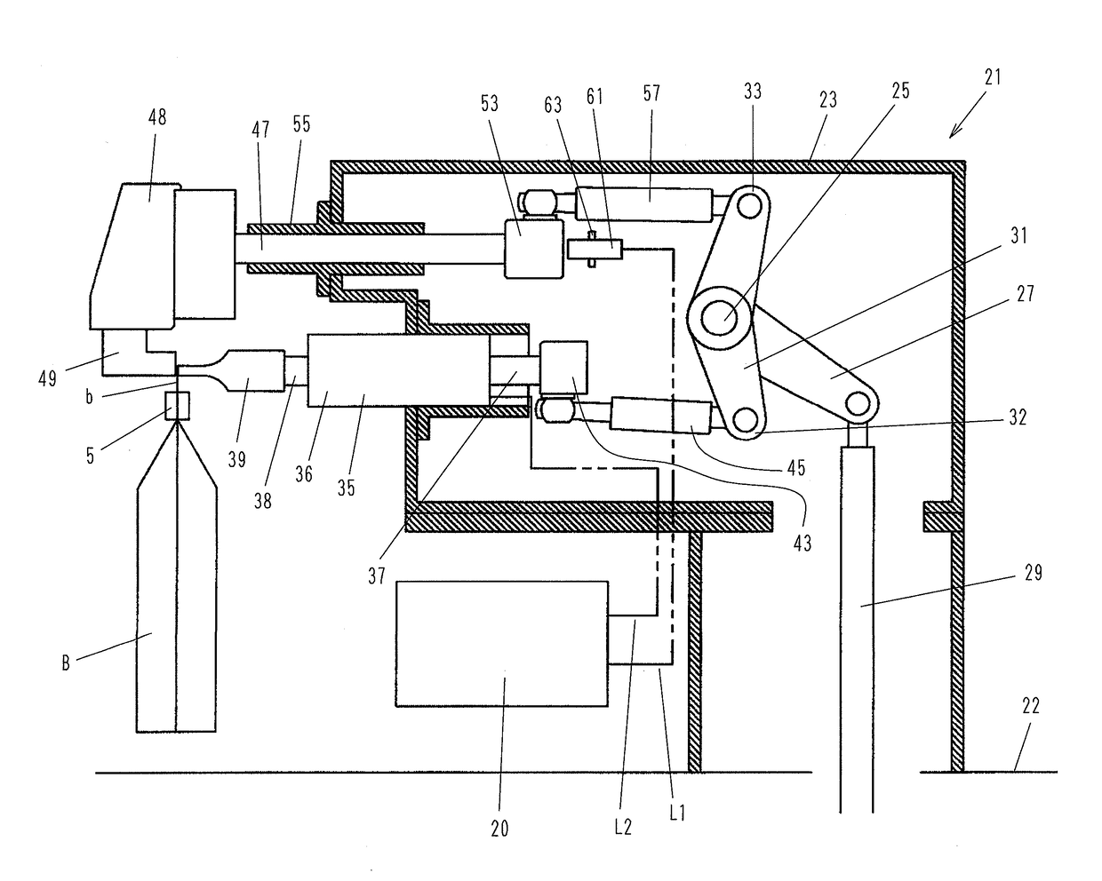
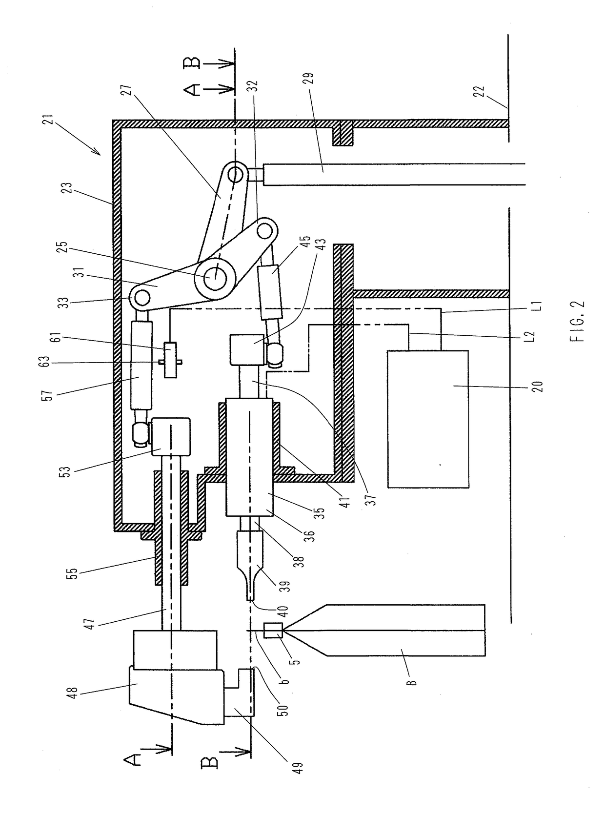
[0040]Next, the sealing apparatus 21 according to the present invention will be explained in detail with reference to FIGS. 2 to 6. FIG. 2 is a sectional side view showing the structure of the sealing apparatus 21, illustrating the sealing apparatus 21 when a bag B filled with a material to be packed at the previous step has moved to and stopped at the station VI. At this time, the sealing apparatus 21 has not yet been activated. FIGS. 3 and 4 are sectional views taken along the lines A-A and B-B, respectively, in FIG. 2.
[0041]It should be noted that, in the following embodiments of the present invention, the bag B is ultrasonically sealed along the edge of the bag mouth b. The reason for this is as follows. Ultrasonic sealing has the advantage of being capable of preventing biting of foreign matter, as has been stated above. However, if the bag B is ultrasonically sealed at a position away from the edge of the bag mouth b, the bag mouth b is open above the sealed portion; therefore...
third embodiment
[0058]FIG. 8 is a sectional side view of an ultrasonic sealing apparatus 75 showing the ultrasonic sealing apparatus 75 in standby position. FIG. 9 is a sectional view taken along the line C-C in FIG. 8. In the figures, reference numeral 76 denotes an anvil. The anvil 76 is secured through an insulator 79 to the lower side of an anvil support member 78 attached to the distal end of a sliding shaft 47 sliding through the guide 55 secured to the frame 23. The insulator 79 prevents formation of a closed circuit which would otherwise be formed between the anvil 76 and the horn 39 through the anvil support member 78, the sliding shaft 47, the guide 55, the frame 23, and the vibrator 35, or between the anvil 76 and the horn 39 through the anvil support member 78, the sliding shaft 47, the second connecting rod 57, the forked lever 31, the first connecting rod 45, and the vibrator 35, when the pressing surface 40 of the horn 39 and a pressing surface 77 of the anvil 76 directly contact ea...
PUM
 Abstract
Description
Claims
Application Information
 - R&D
- Intellectual Property
- Life Sciences
- Materials
- Tech Scout
- Unparalleled Data Quality
- Higher Quality Content
- 60% Fewer Hallucinations
Browse by: Latest US Patents, China's latest patents, Technical Efficacy Thesaurus, Application Domain, Technology Topic, Popular Technical Reports.
© 2025 PatSnap. All rights reserved.Legal|Privacy policy|Modern Slavery Act Transparency Statement|Sitemap|About US| Contact US: help@patsnap.com