Driver circuit for touch panel

a technology of driver circuit and touch display panel, which is applied in the field of display, can solve the problems of not being suitable for the narrow border design of the touch display panel, occupying too much space by the driver circuit, etc., and achieves the effect of reducing the layout space occupied, simplifying the circuit structure, and reducing the border width of the touch display

Active Publication Date: 2018-02-01
WUHAN CHINA STAR OPTOELECTRONICS TECH CO LTD
View PDF0 Cites 1 Cited by
  • Summary
  • Abstract
  • Description
  • Claims
  • Application Information

AI Technical Summary

Benefits of technology

[0010]The object of the present invention is to provide a touch driver circuit, simplifying the circuit structure by reducing the number of the elements and the number of signals, reducing the space occupied by the touch driver circuit so as to reduce the border width of the touch display panel to realize the narrow-border touch display panel.
[0020]Compared to the known techniques, the present invention provides the following advantages: the present invention provides a touch driver circuit, by only using a select signal to control the operation of the transport gates to realize the output of the valid pulse touch driver signal and constant low voltage signal. The circuit structure is simplified, and removes a plurality of elements and two control signals so as to reduce the layout space occupied by the touch driver circuit as well as reduced the border width of the touch display to realize narrow border design for touch display panel.

Problems solved by technology

Although the touch driver circuit in the above known hybrid embedded touch display panel can effectively reduce the number of output ports in the integrated circuit (IC), the number of the signals and elements are too many, which leads to occupying too much space by the touch driver circuit, and not suitable for narrow border design of the touch display panel.

Method used


Image

  • Driver circuit for touch panel
  • Driver circuit for touch panel
  • Driver circuit for touch panel

Examples


Embodiment Construction

[0027]To further explain the technical means and effect of the present invention, the following refers to embodiments and drawings for detailed description.

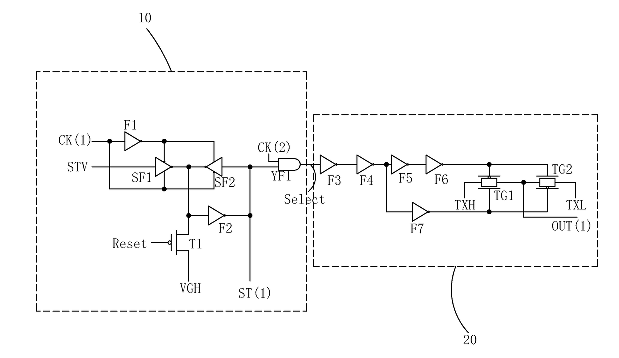
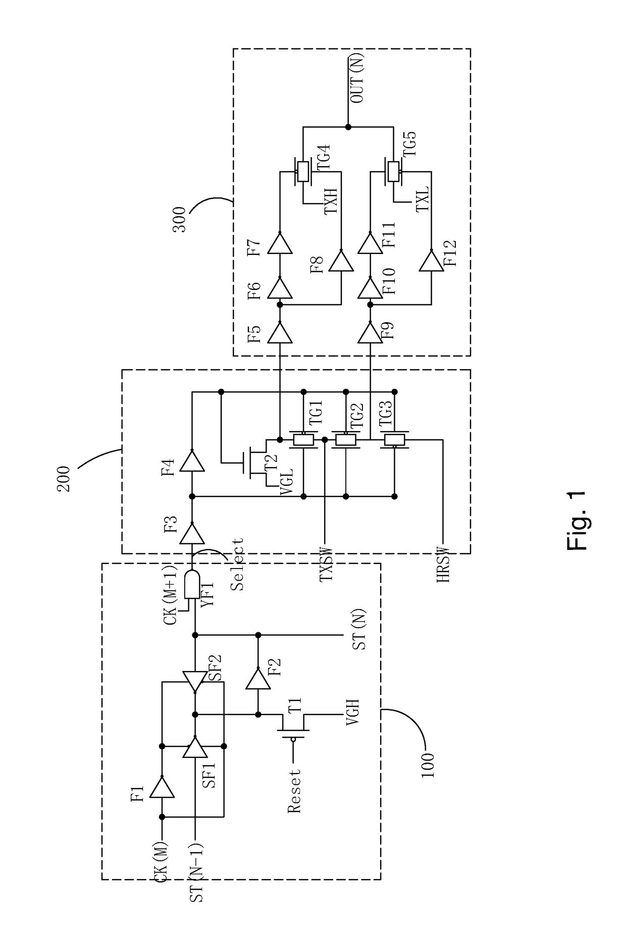
[0028]Refer to FIG. 3 and FIG. 4. The present invention provides a touch driver circuit, which comprises a plurality of cascading touch driver units, each touch driver unit comprising: a cascading unit 10, and an output unit 20.

[0029]For a positive integer N, except the first touch driver unit, in an N-th touch driver unit:

[0030]The cascading unit 10 comprises: a first NOT gate F1, with an input end connected to an M-th clock signal CK(M) and an output end connected to a low voltage control end of a first tri-state NOT gate SF1 and a high voltage control end of a second tri-state NOT gate SF2;

[0031]The first tri-state NOT gate SF1, having an input end connected to a cascading signal ST(N−1) of an (N−1)-th touch driver unit, an output end connected to an output end of second tri-state NOT gate SF2, the high voltage control end con...


PUM


Abstract

The invention provides a touch driver circuit, by only using a select signal (Select) to control the operation of transport gates (TG1, TG2) to realize output of a valid pulse touch driver signal (TXH) and a constant low voltage signal (TXL). The circuit structure is simplified, and removes a plurality of elements and two control signals so as to reduce the layout space occupied by the touch driver circuit as well as reduced the border width of the touch display to realize narrow border design for touch display panel.

Description

BACKGROUND OF THE INVENTION1. Field of the Invention[0001]The present invention relates to the field of display, and in particular to a driver circuit for touch panel.2. The Related Arts[0002]In the rapid development of display technology, the liquid crystal display (LCD) and organic light-emitting diode (OLED) display have the advantages of high display quality, low power-consumption, and thin, and are widely used in applications, such as, mobile phone, TV, personal digital assistant (PDA), digital camera, notebook PC, desktop PC, and so on, and become the mainstream display technology.[0003]A touch panel provides an effective and direct interface for human-machine interaction interface. By integrating the touch panel with the flat display into a touch display panel, the flat display panel with a touch control capability allows the users to operate in a more direct, intuitive and convenient way. The embedded touch display panel refers to the type that integrates the touch panel and...

Claims


Application Information

Patent Timeline
Patent Type & Authority Applications(United States)
IPC IPC(8): G06F3/041
CPCG06F3/0412G06F3/0416G06F3/041
Inventor GONG, QIANG
Owner WUHAN CHINA STAR OPTOELECTRONICS TECH CO LTD
Why Eureka
Try Eureka