Chain closing link
a closing link and chain technology, applied in the direction of driving chains, cycles, transportation and packaging, etc., can solve problems such as undesired detachmen
- Summary
- Abstract
- Description
- Claims
- Application Information
AI Technical Summary
Benefits of technology
Problems solved by technology
Method used
Image
Examples
first embodiment
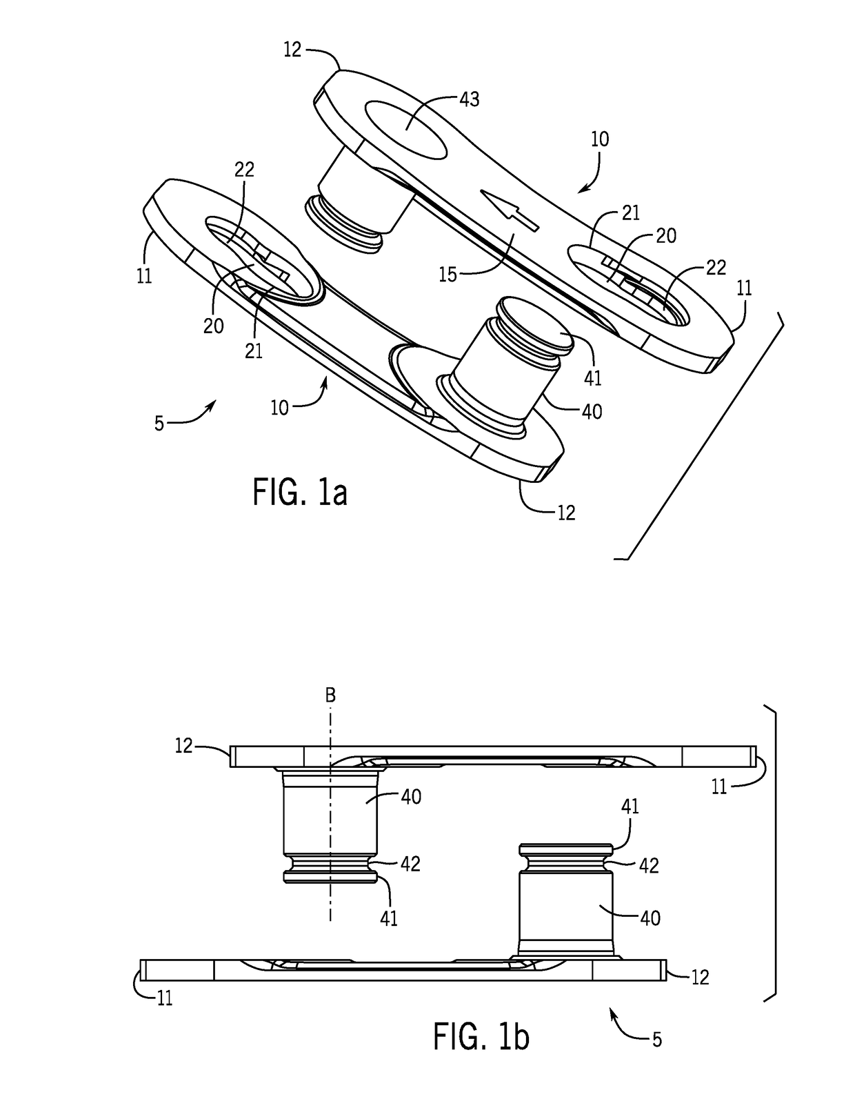
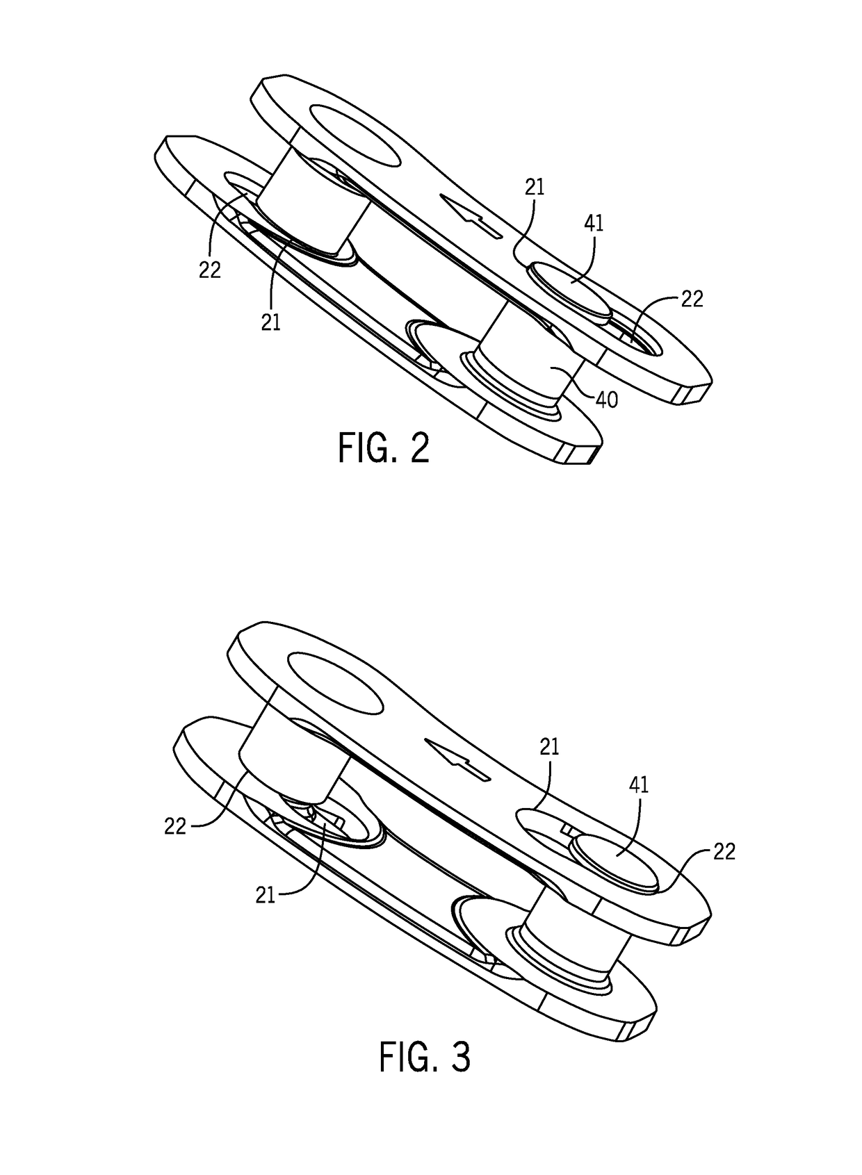
[0088]FIG. 7 shows a closing plate 10. The shape of the closing plate 10 is clearly evident in the plan view in FIG. 7a. Thus, the closing plate 10 is of asymmetrical design along its longitudinal axis V. The connecting region 15, which is arranged between the first end region 11 and the second end region 12, is not tapered as in the prior art. The connecting region 15 has a concave peripheral region 14 and a convex peripheral region 13. The plan view also shows the slot 20 and the pin bore 16 with its depression 16b. The depression 16b creates space for the riveting of the pin foot and accommodates the deformed material of the pin foot. This prevents the situation where the deformed material of the pin foot projects beyond the surface of the closing plate 10 and collides with other parts of the bicycle drive, e.g. during gear change. The recess 15a in the connecting region 15 is clearly evident in that side view of the closing plate 10 which is illustrated in FIG. 7b. The connectin...
second embodiment
[0090]FIGS. 8a-d show the closing plate 10′. The closing plates 10 and 10′ differ merely by way of the enlarged depression 16b′ of the pin bore 16 on the outer side and the resulting enlarged projection 16a′ on the inner side. The enlarged depression 16b′ can accommodate more deformed pin material. The projection 16a′ provides yet more stability in the region of the pin bore 16. It is also the case that the slot 20, in this exemplary embodiment, has a projection 20a on the inner side of the closing plate 10′. This projection 20a is also produced by material deformation of the plate 10′ and contributes to the stability in the region of the slot 20. The projection 20a slopes down in the direction of the first end region 11 and can be seen particularly clearly in the side view and in the perspective view.
third embodiment
[0091]FIG. 9a shows the outer side, and FIG. 9b shows the inner side, of the closing plate 10″. This closing plate 10″ differs from the other two on account of its contour. In this case, one peripheral region 14 is of concave design and the other peripheral region 17 is of rectilinear design. The concave peripheral region 14 follows the shape of the rest of the outer link plates and inner link plates and the rectilinear peripheral region 17 is a good compromise between stability and rolling behavior on the upper chain rollers of the rear derailleur. It is also the case that the rectilinear peripheral region 17 has a bevel 17a, which facilitates the engagement of a tooth in the interspace between two mutually opposite closing plates. The bevels 13a, 14a, 17a in all the embodiments form a kind of funnel shape with the largest possible inside width for the engaging teeth.
[0092]FIG. 9a also clearly shows the oblique positioning of the slot 20 in relation to the longitudinal axis V of th...
PUM
 Abstract
Description
Claims
Application Information
 - R&D
- Intellectual Property
- Life Sciences
- Materials
- Tech Scout
- Unparalleled Data Quality
- Higher Quality Content
- 60% Fewer Hallucinations
Browse by: Latest US Patents, China's latest patents, Technical Efficacy Thesaurus, Application Domain, Technology Topic, Popular Technical Reports.
© 2025 PatSnap. All rights reserved.Legal|Privacy policy|Modern Slavery Act Transparency Statement|Sitemap|About US| Contact US: help@patsnap.com


