
Method for forming three-dimensional decoration on wall surface, and three-dimensional decoration formed using the method

a three-dimensional decoration and wall surface technology, applied in the field of three-dimensional decoration on the wall surface, and three-dimensional decoration formed using the method, can solve the problems of increased cost, increased cost of mold formation, and inability to realize three-dimensional decoration in a flat manner, so as to achieve less change and less likely to be peeled off

Active Publication Date: 2018-01-18
KU BON JOON
View PDF2 Cites 0 Cited by
  • Summary
  • Abstract
  • Description
  • Claims
  • Application Information

AI Technical Summary

Benefits of technology

This patent describes a technique for creating decorative patterns on surfaces using cement plastering. This approach eliminates the need for molds, reducing costs and allowing for more complex forms. The use of silicon and pigments can also improve the clarity and durability of the colors. Overall, this method simplifies and streamlines the process of creating decorative patterns on walls.

Problems solved by technology

This flat manner may not realize three-dimensional decoration.
In addition, since the three-dimensional ornament object needs to be transported to an installation site thereof, an additional cost is incurred.
This leads to a larger cost to form the mold.
In addition, it takes more labor and logistic cost to transfer the manufactured ornament object to the installation site.
Moreover, when the three-dimensional ornament object has a complex and elaborate shape, it may be difficult to form the three-dimensional ornament object using a mold.

Method used


Image

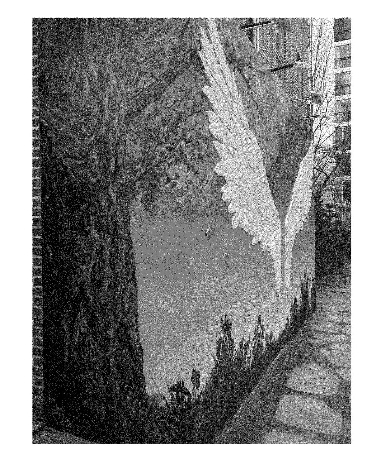
  • Method for forming three-dimensional decoration on wall surface, and three-dimensional decoration formed using the method
  • Method for forming three-dimensional decoration on wall surface, and three-dimensional decoration formed using the method
  • Method for forming three-dimensional decoration on wall surface, and three-dimensional decoration formed using the method

Examples


Embodiment Construction

[0025]Examples of various embodiments are illustrated and described further below. It will be understood that the description herein is not intended to limit the claims to the specific embodiments described. On the contrary, it is intended to cover plate alternatives, modifications, and equivalents as may be included within the spirit and scope of the present disclosure as defined by the appended claims.

[0026]Spatially relative terms, such as “beneath,”“below,”“lower,”“under,”“above,”“upper,” and the like, may be used herein for ease of explanation to describe one element or feature's relationship to another element s or feature s as illustrated in the figures. It will be understood that the spatially relative terms are intended to encompass different orientations of the device in use or in operation, in addition to the orientation depicted in the figures. For example, if the device in the figures is turned over, elements described as “below” or “beneath” or “under” other elements o...


PUM


Abstract

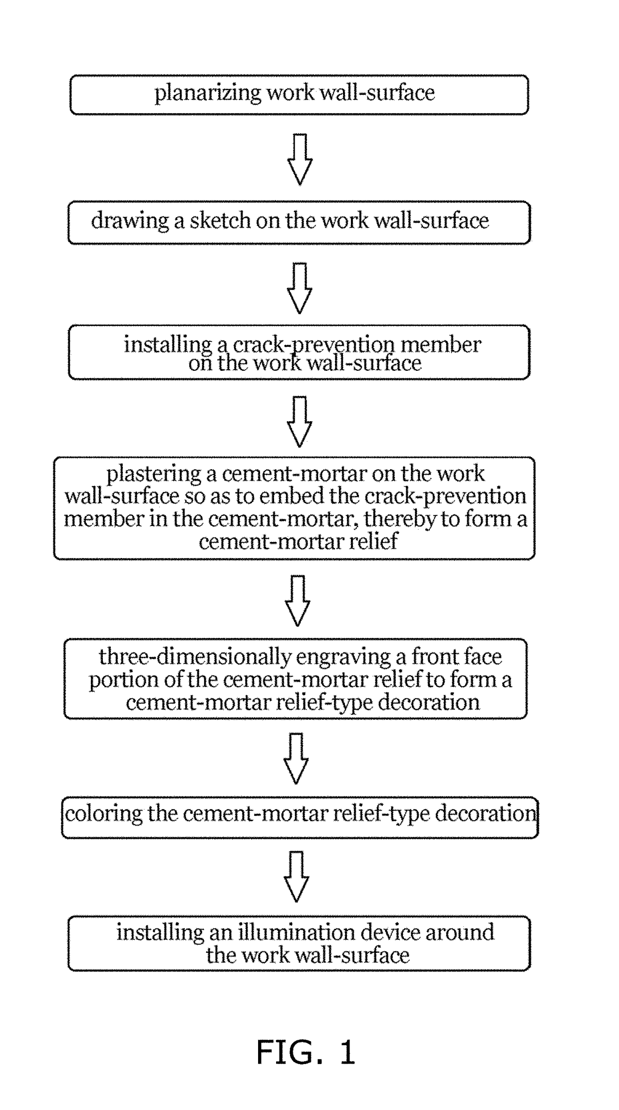
There is provided a method for forming a three-dimensional decoration on a wall surface, wherein the method comprises: drawing a sketch on the work wall-surface; installing a crack-prevention member on the work wall-surface to suppress a separation between the three-dimensional decoration and the wall surface, wherein the crack-prevention member is disposed in a first region corresponding to the sketch; plastering a cement-mortar in the first region on the work wall-surface so as to embed the crack-prevention member in the cement-mortar, thereby to form a cement-mortar relief; three-dimensionally engraving a front face portion of the cement-mortar relief to form a cement-mortar relief-type decoration as the three-dimensional decoration; and coloring the cement-mortar relief-type decoration using a mixture of silicon as a binder and coloring pigments.

Description

BACKGROUNDField of the Present Disclosure[0001]The present disclosure relates to a method for forming a three-dimensional decoration on a wall surface, and a three-dimensional decoration formed using the method. More particularly, the present disclosure relates to a method for forming a three-dimensional decoration on a wall surface wherein the three-dimensional decoration has various and complex designs and is formed without a mold.Discussion of Related Art[0002]In terms of urban beauty or building value, the wall of a building or a boundary-defining wall may be beautifully decorated. The most typical method for the decoration is to paint the boundary-defining wall or the wall of the building.[0003]However, when painting the boundary-defining wall or the wall of the building, the wall or wall of the building is decorated in a flat manner. This flat manner may not realize three-dimensional decoration. Thus, a three-dimensional decoration method may be used to decorate the wall more ...

Claims


Application Information

Patent Timeline
IPC IPC(8): G09F19/22E04F13/04E04F13/08G09F13/02
CPCG09F19/226E04F13/047E04F13/0871G09F13/02
Inventor KU, BON JOON
Owner KU BON JOON
Learn More