
A system and method for callibrating and controlling pressure

a technology of pressure generation and control system, applied in the direction of liquid/fluent solid measurement, volume flow testing/calibration, instruments, etc., can solve the problems of increasing the probability of system leakage, increasing cost and complexity, and limited pressure range of devices, so as to reduce the number of connections required

Inactive Publication Date: 2018-01-18
SETRA SYST
View PDF3 Cites 12 Cited by
  • Summary
  • Abstract
  • Description
  • Claims
  • Application Information

AI Technical Summary

Benefits of technology

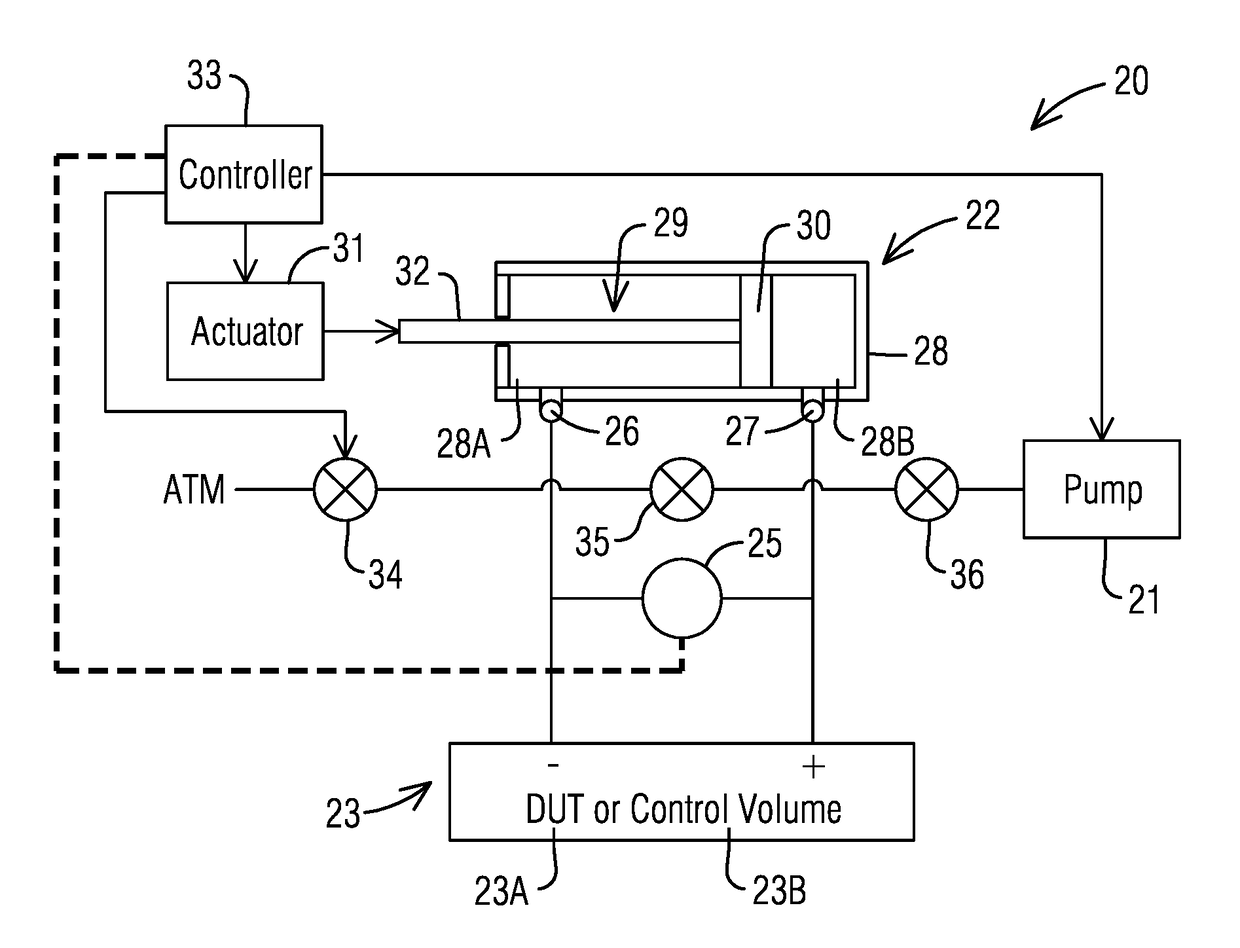
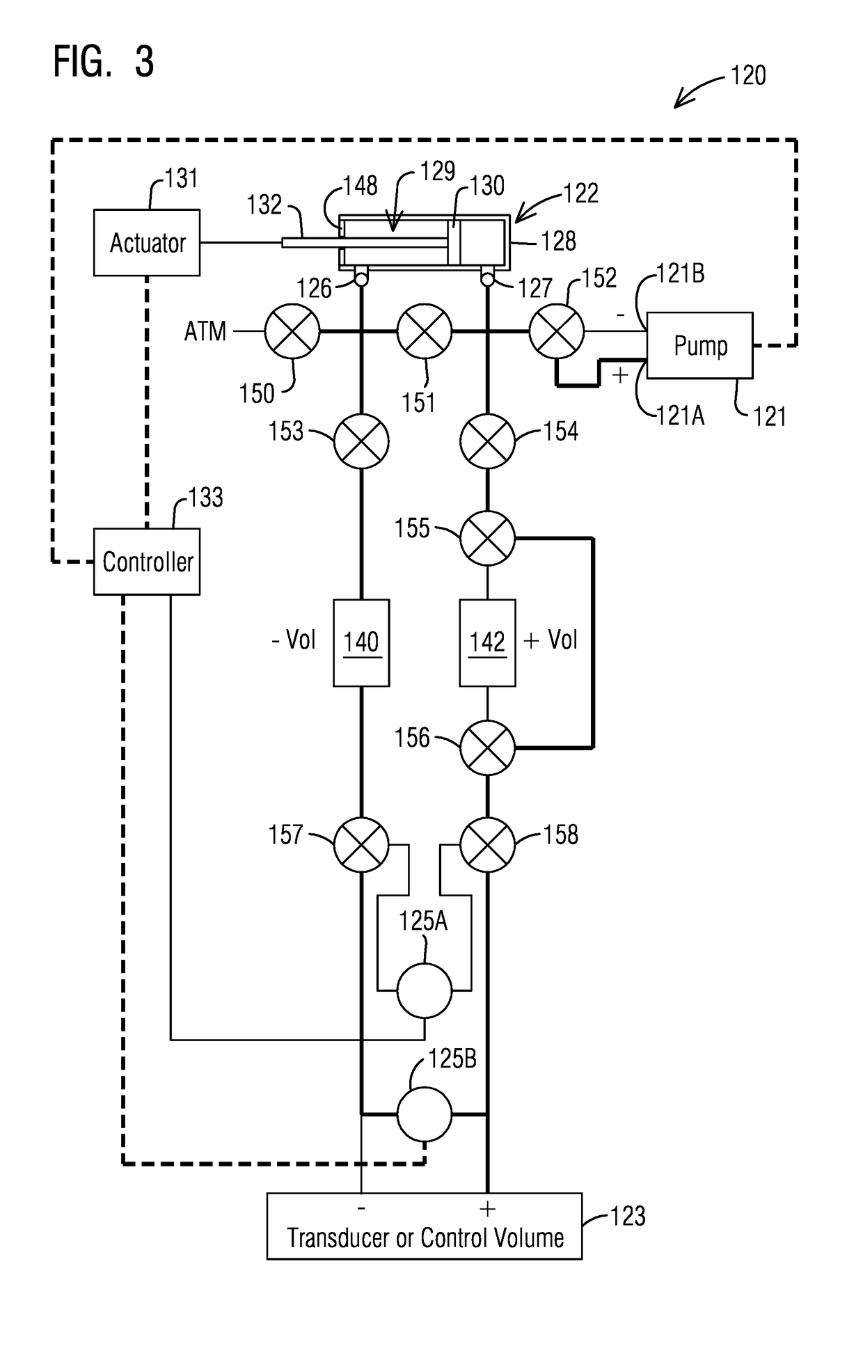
The invention integrates pressure chambers and a valve manifold into a single unit, reducing the number of connections required to operate the system. This is achieved by a manifold block with two sections. The second section includes a plurality of ports for fluid flow, allowing for the valves and components of the pressure control system to be surface mounted on the manifold block and further integrating the system.

Problems solved by technology

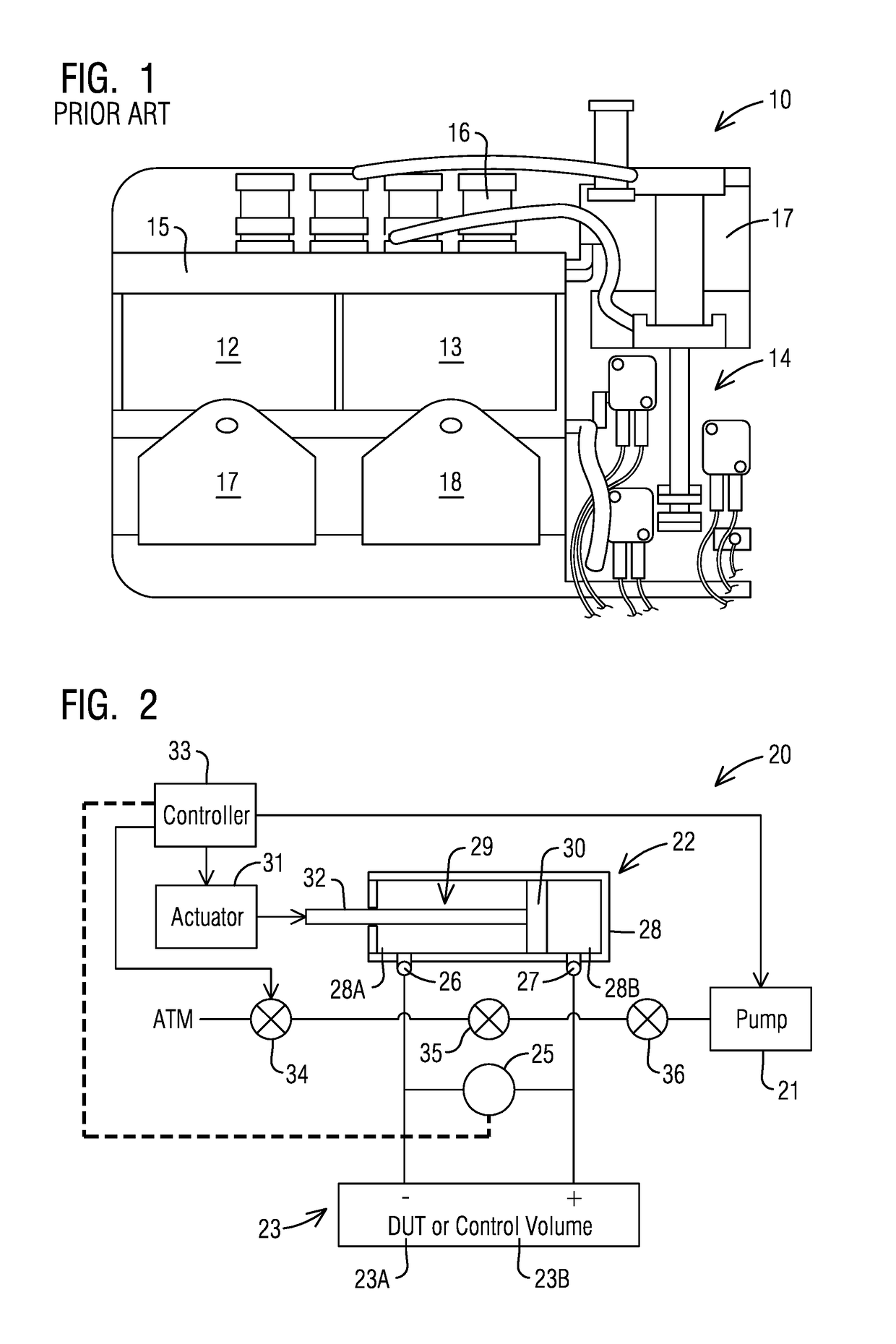
In particular, the primary disadvantage of pressure control as incorporated in the Setra Model 869 is that because such devices have separate solenoid assemblies relative to a manifold and the two volumes, there exists a higher number of pressure connections, which increase the probability of system leaks and also increases cost and complexity.
Another disadvantage is that such devices are limited in pressure ranges because the piston and cylinder assembly can pressurize or depressurize in the range of −1 psi to +1 psi.
In order to control pressure levels outside this range requires a separate air supply, which also results in increased cost and complexity and limits the capability of field use.
Furthermore, a particular disadvantage of pressure control using air pumps is that the pumps produce an oscillatory pressure control that reduces accuracy.
In addition, the accuracy of the pressure depends on the skill of the operator, which increases the possibility of error or variance.

Method used


Image

  • A system and method for callibrating and controlling pressure
  • A system and method for callibrating and controlling pressure
  • A system and method for callibrating and controlling pressure

Examples


second embodiment

[0055]a pressure calibration and control system 300 is shown in FIGS. 7 and 8, wherein the manifold block 361 takes the form of a planar block member with all components external to the first and second chambers 340, 342 and plurality of ports 370 (FIG. 8) are mounted to an external surface of the manifold block 361. Namely, the valves 350-357, actuator 331, piston cylinder assembly 322, pump 321 and reference pressure transducer 325 are all mounted to an external top surface 330 of the manifold block 361. Again, a controller 333 is provided on a stand-alone PCBA and electrical connections are provided as necessary to drive, control or communicate with components such as the pump 321, the actuator 331or the reference pressure transducer 325.

[0056]With respect to FIG. 8, a gasket and cover plate assembly 350 is shown removed revealing the first and second chambers 340, 342, which define the first section 362 of the manifold block 361which is integrally formed with a second section 36...

third embodiment

[0057]the pressure calibration and control system 420 is shown in FIGS. 9 and 10, and includes further integration of components by internally mounting or fabricating components of the piston / cylinder assembly 422 and / or the linear coupling components. As shown, from a top view in FIG. 9, the first and second chambers 440, 442 form the first section 462 of the manifold block 461. The second section 465 of the manifold block 461 is disposed above and between, or entirely between, or below and between the first and second chambers 440, 442. Although, not specifically shown, ports are formed in the second section for fluid flow in and out of the chambers 440, 442.

[0058]In reference to FIG. 10, the cylinder 428 of the piston / cylinder assembly 422 is formed in the second section 465 of the manifold block 461 and is sealed at one end by a bushing 475, and the piston 429 is moveable linearly within the cylinder 428. As further shown, the actuator 431 is mounted at one end of the manifold b...


PUM


Abstract

A system for controlling pressure associated with a volume may comprising a pump and piston / cylinder assembly, both in fluid communication with a volume of a closed fluid system. In addition, the system may comprise an actuator operatively connected to the actuator and pump to control fluid flow and pressurization or depressurization of the volume and / or fluid flow system. The pump is activated to generate a first pressure level of the closed fluid system and when this first pressure level is reached the actuator is activated to drive the piston / cylinder assembly to reach a pressure set point from the first pressure level. The system may be used as a calibrator or a pressure controller for pressure differentials, gauge pressure or absolute pressure.

Description

[0001]This application claims benefit of the Jan. 24, 2015 filing date of application 62 / 107,361 which is incorporated by reference herein.FIELD OF THE INVENTION[0002]Embodiments of the invention described herein relate to a system and method for generation of low and high pressures which are accurate and controllable. More specifically, the embodiments of the invention pertain to systems and method for use in calibrating devices, which will be referred to as devices under test (DUT) such as pressure transducers, pressure switches and pressure gauges as well as generation of accurate and precise pressures used in process control. These devices (DUT) are used for measurement of low pressures in applications such as HVAC (Heating, Ventilating and Air Conditioning) Systems.BACKGROUND OF THE INVENTION[0003]A low differential pressure between two areas such as the pressure differential between two chambers or rooms is required for certain industrial and test facilities, including semi-co...

Claims


Application Information

Patent Timeline
IPC IPC(8): G01L27/00G01F25/00G01L19/00F15B19/00
CPCG01L27/005G01F25/003G01L27/007G01L19/0015G01F25/0092G01F25/0038F15B19/002G01F25/13G01F25/17
Inventor BATISTA, ANTHONY T.HENRY, SHAWN OSCARROBINS, JOSHUA SHUFORDCHAGNOT, J. MATTHEWBEISHLINE, ERIC CHRISTOPHERPINTO, GINO AMARO
Owner SETRA SYST
Learn More