
Method of manufacturing a launder and launder

a manufacturing method and laundering technology, applied in solvent extraction, material recovery, separation processes, etc., can solve the problems of difficult local suppliers, oversize transportation, and inability to produce launders, etc., to achieve convenient re-location and recycling, flexible capacity, and more capacity

Active Publication Date: 2018-01-18
METSO OUTOTEC (FINLAND) OY
View PDF0 Cites 0 Cited by
  • Summary
  • Abstract
  • Description
  • Claims
  • Application Information

AI Technical Summary

Benefits of technology

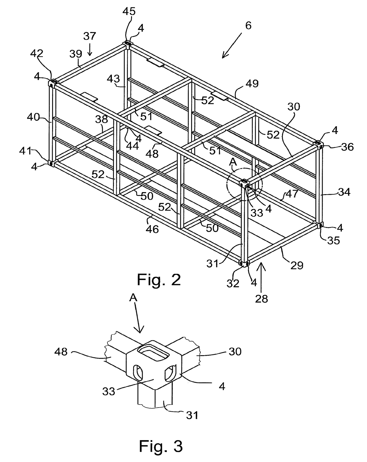
The invention is a launder element module that can be manufactured in a factory environment and shipped to the installation site. The module is standard compatible with shipping containers, which makes it easy to handle and transport. The module can be used in a shipping container and has the same benefits as a normal shipping container. The module can be easily relocated and recycled. The launder element module conforms to the shipping container standards and has all the benefits of a container. The module has a self-supporting framework structure and a shell made of fiber-reinforced plastic composite. The shell is gas-tight and smooth to minimize turbulences and electrostatic charging. The invention facilitates flexible capacity and cost-effectiveness.

Problems solved by technology

There has not been a possibility for the productization of launders.
The present launders have nonstandard transport dimensions requiring oversize transport which is expensive.
This causes problems because of the crucial influence of local factors.
It may be difficult to get local suppliers.
It has been difficult to control the quality of the site work by local suppliers.
Further, the maintenance of the present launders requires a long downtime of the whole solvent extraction settler with which the launder requiring maintenance is connected.

Method used


Image

  • Method of manufacturing a launder and launder
  • Method of manufacturing a launder and launder
  • Method of manufacturing a launder and launder

Examples


Embodiment Construction

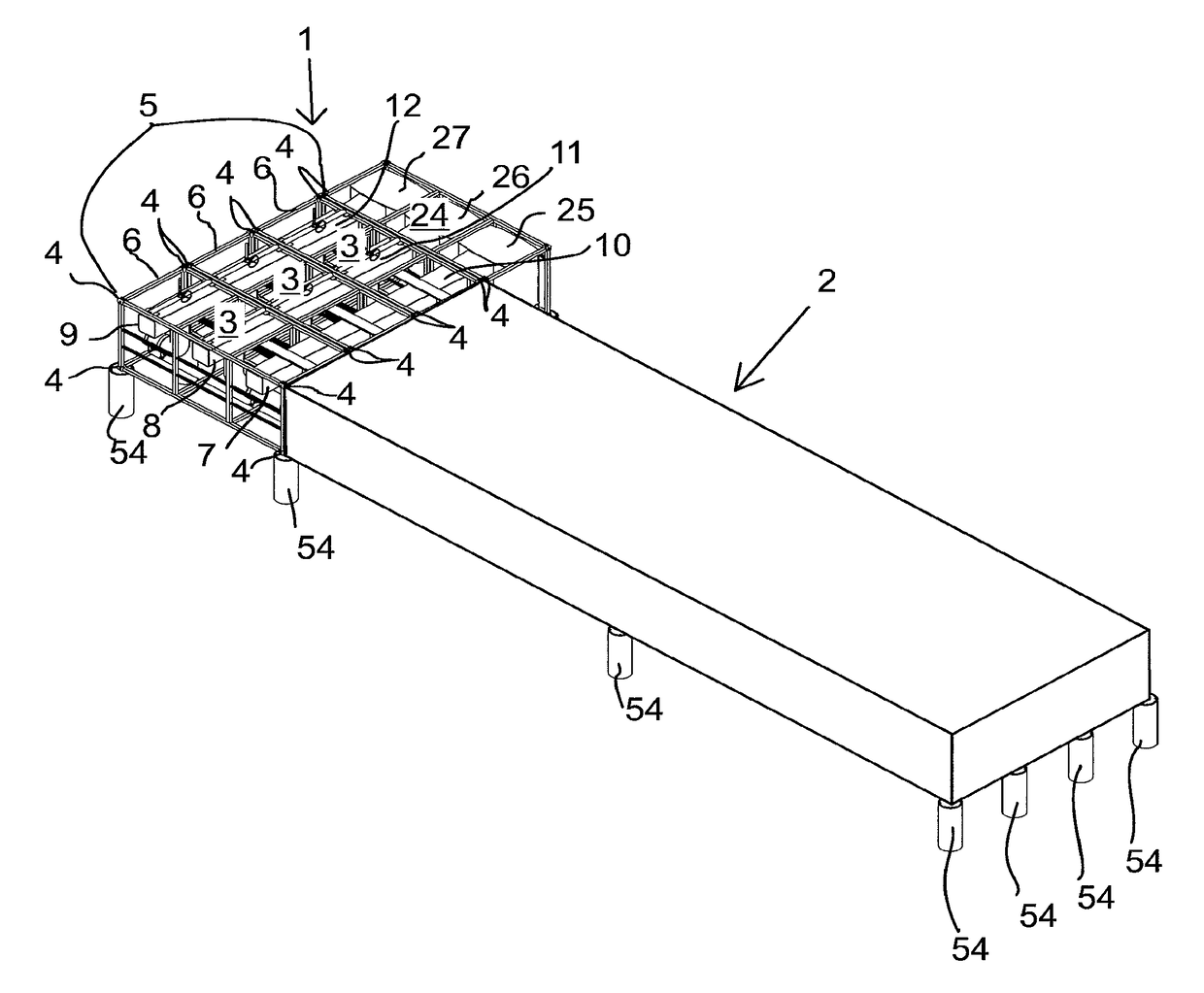
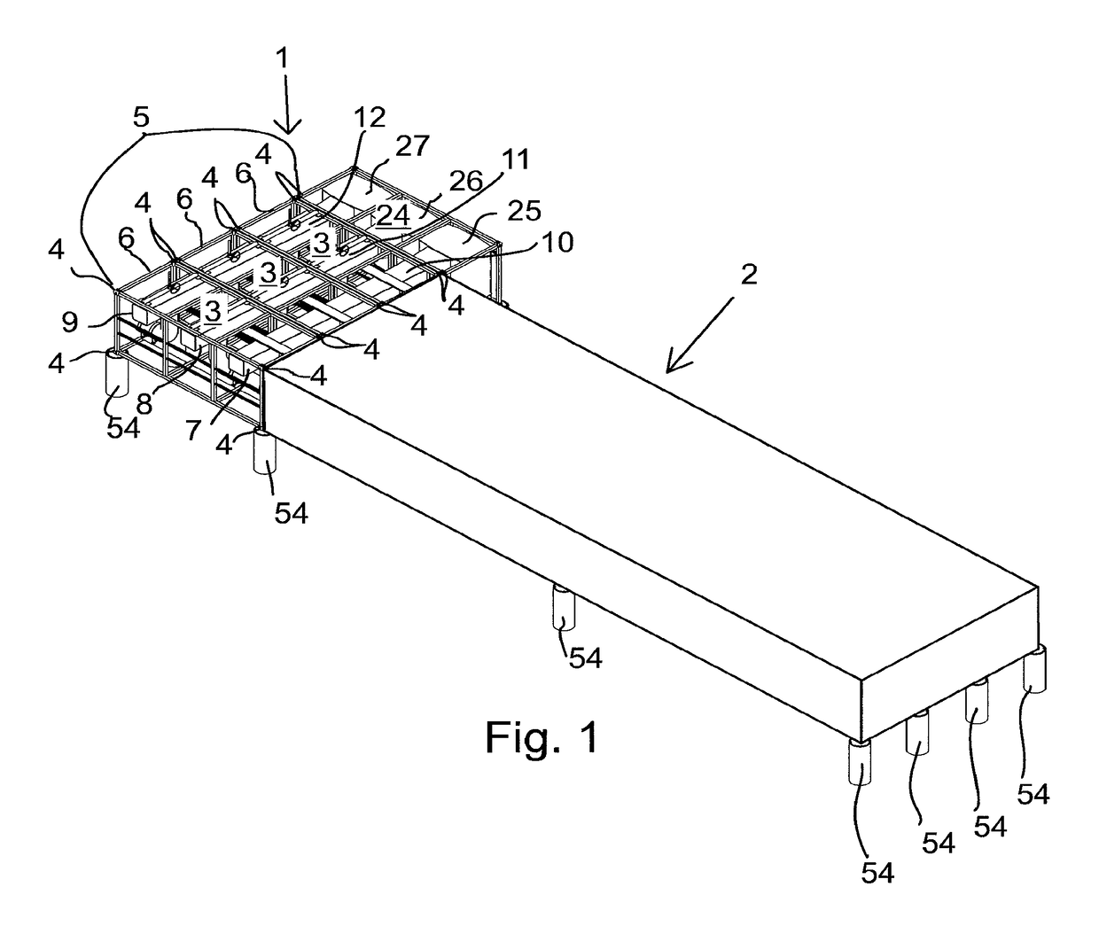
[0056]FIG. 1 shows one embodiment of a solvent extraction settler which is used in hydrometallurgical liquid-liquid extraction processes for separating solutions mixed in a dispersion into different solution phases. The launder 1 is connected to the settler 2. The dispersion pump and mixers which are used to prepare the dispersion are not shown in FIG. 1. The settler 2, which is not part of this invention, is shown only schematically. The settler 2 may be of a conventional type comprising a large tank built on the site, or it may be modular and composed of a number of prefabricated, ISO shipping container compatible settler element modules transferred and installed at the site into a complete settler as disclosed in another patent application filed in parallel with this application.

[0057]The launder 1 may have two functions. It may be arranged to feed dispersion to the settler 2 (see FIG. 4) and it may be arranged to receive and discharge the separated solutions obtained from the se...


PUM

PropertyMeasurementUnit
areaaaaaaaaaaa
widthaaaaaaaaaa
widthaaaaaaaaaa

Abstract

A method of manufacturing a launder (1) to be used in co-operation with a solvent extraction settler (2) comprises manufacturing at the site of manufacture, such as in an engineering workshop, a plurality of self-supporting launder element modules (3), each having exterior dimensions, strength and handling and securing means (4) conforming to shipping container standards, transporting the launder element modules (3) to the site of installation as normal freight by transport equipment, such as trucks, trailers and container ships, capable of handling and transporting shipping container standard compatible units, and assembling at the site of installation the launder element modules (3) into a module group (5) forming a complete launder. The launder (1) comprises a launder module group (5) consisting of self-supporting launder element modules (3), each having exterior dimensions, strength and handling and securing means (4) conforming to shipping container standards to enable shipping container standard compatible transportability.

Description

FIELD OF THE INVENTION[0001]The present invention relates to a method of manufacturing a launder to be used in co-operation with a solvent extraction settler adapted for hydrometallurgical liquid-liquid extraction processes. Further, the invention relates to a launder.BACKGROUND OF THE INVENTION[0002]In a typical mixer-settler, in the first step, the aqueous and organic phases are pumped into a mixer or mixers in order to achieve a uniform liquid-liquid dispersion and a small droplet size. In the VSF® technology (stands for Vertical Smooth Flow) developed by the applicant this first step is performed in a pump-mixer called Dispersion Overflow Pump (DOP( ) (disclosed e.g. in document U.S. Pat. No. 5,662,871) and in a set of two SPIROK® helical mixers (disclosed in e.g. document U.S. Pat. No. 5,185,081). After mixing, the dispersion is fed into a settler. The settler is typically a large tank which is square in plan and its square area is about several hundred square meters. Dispersio...

Claims


Application Information

Patent Timeline
Patent Type & Authority Applications(United States)
IPC IPC(8): B01D11/04C22B3/02C22B3/26C22B3/22
CPCY02P10/234C22B3/0005C22B3/22C22B3/02B01D11/0446Y10T29/49826C22B3/26Y02P10/20
Inventor VAARNO, JUSSISAARIO, RAMIFREDRIKSSON, HENRI
Owner METSO OUTOTEC (FINLAND) OY
Learn More