
Deflector for gas turbine engine combustors and method of using the same

a technology of combustors and deflectors, which is applied in the direction of continuous combustion chambers, combustion processes, lighting and heating apparatus, etc., can solve the problems of increasing combustion dynamics and flame instability, reducing the efficiency and durability of combustor and overall gas turbine engines

Inactive Publication Date: 2018-01-11
GENERAL ELECTRIC CO
View PDF3 Cites 25 Cited by
  • Summary
  • Abstract
  • Description
  • Claims
  • Application Information

AI Technical Summary

Benefits of technology

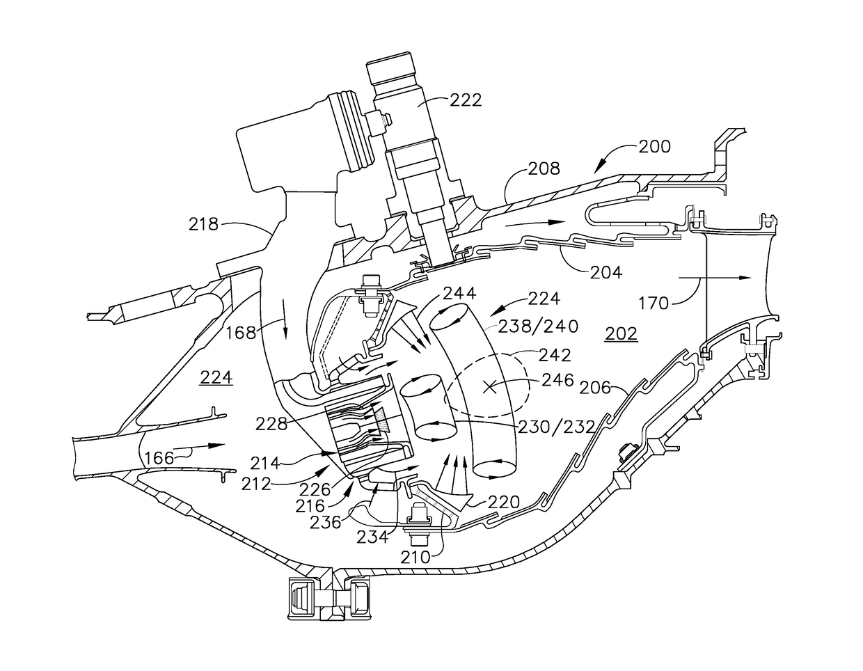
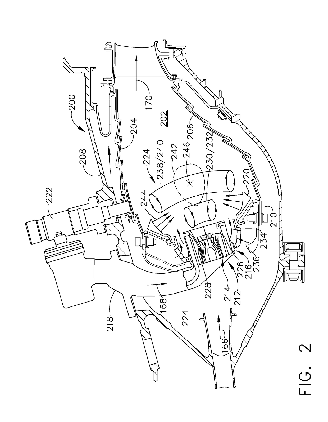
This patent describes a device called a deflector that is added to a gas turbine engine's combustor. This deflector is designed to help stabilize the flame within the combustor by reflecting thermal radiation back to the fuel and air mixture. This can help improve combustor performance and reduce emissions. The deflector is attached to the combustor's liner and has a small hole that allows the fuel and air mixture to pass through it. This small hole acts as a focal point for the deflector, which helps to keep the flame in the correct position.

Problems solved by technology

Ignitors mounted downstream from the mixers ignite the mixture, and it burns in the combustion chamber.
Lean fuel and air mixtures, however, may increase combustion dynamics and flame instability because of the low temperature flame.
Flame instability and combustion dynamics generally reduces combustor and overall gas turbine engine efficiency and durability.

Method used


Image

  • Deflector for gas turbine engine combustors and method of using the same
  • Deflector for gas turbine engine combustors and method of using the same
  • Deflector for gas turbine engine combustors and method of using the same

Examples


Embodiment Construction

[0012]In the following specification and claims, reference will be made to a number of terms, which shall be defined to have the following meanings.

[0013]The singular forms “a,”“an,” and “the” include plural references unless the context clearly dictates otherwise.

[0014]“Optional” or “optionally” means that the subsequently described event or circumstance may or may not occur, and that the description includes instances where the event occurs and instances where it does not.

[0015]Approximating language, as used herein throughout the specification and claims, may be applied to modify any quantitative representation that could permissibly vary without resulting in a change in the basic function to which it is related. Accordingly, a value modified by a term or terms, such as “about,”“approximately,” and “substantially,” are not to be limited to the precise value specified. In at least some instances, the approximating language may correspond to the precision of an instrument for measu...


PUM


Abstract

A deflector for a gas turbine engine combustor. The combustor includes a liner defining a combustion zone and a mixer assembly configured to supply the combustion zone with a predetermined mixture of fuel and air. The deflector includes a deflector body configured to couple to the liner. The deflector body includes a first surface configured to reflect thermal radiation to a predetermined focal area, and an aperture extending through the deflector body and configured to receive the mixer assembly therethrough.

Description

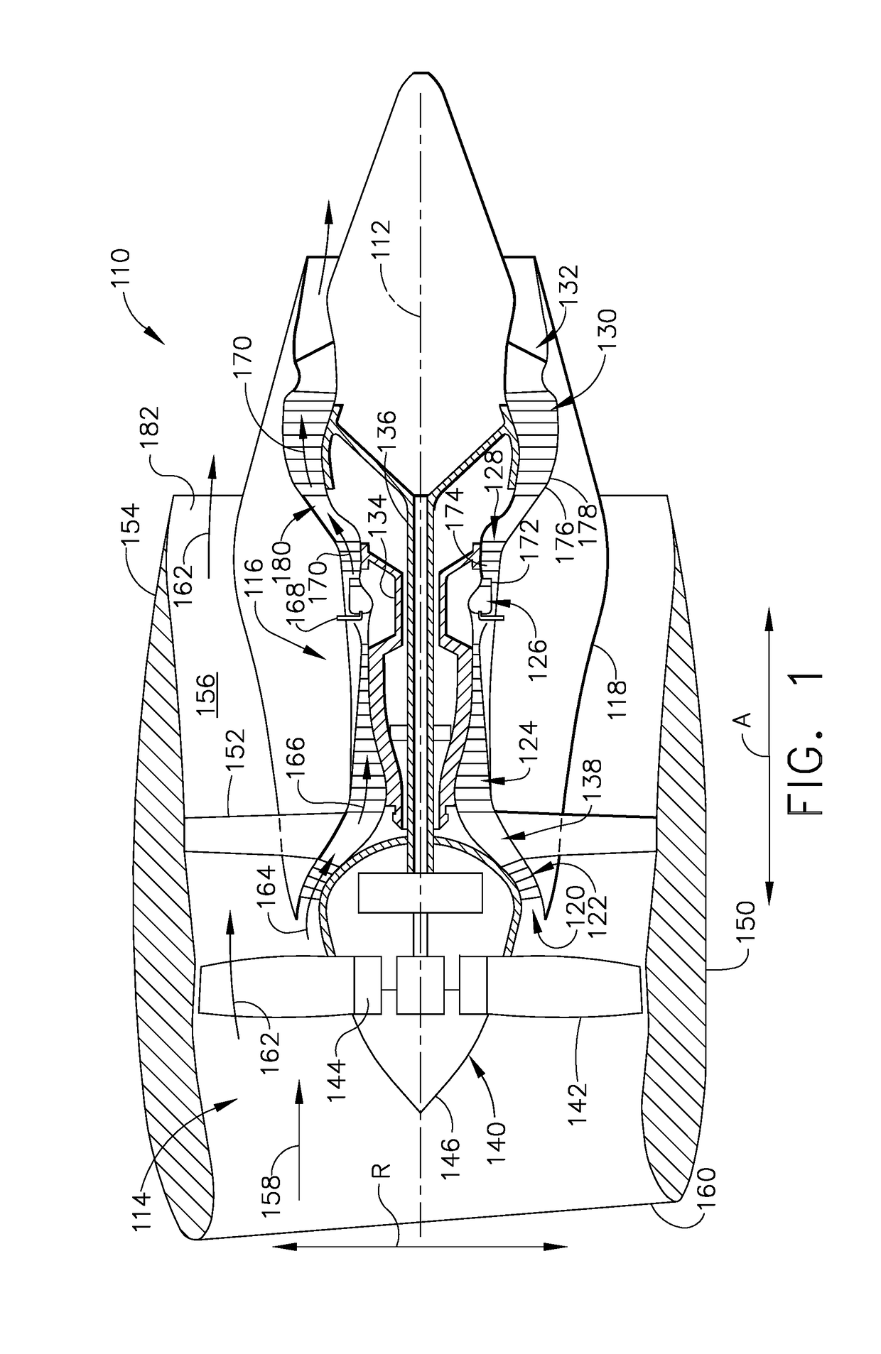
BACKGROUND[0001]The field of the disclosure relates generally to gas turbine engines and, more particularly, to deflectors for use in gas turbine engine combustors.[0002]Combustors are used to ignite fuel and air mixtures in gas turbine engines to generate high energy working gases. Known combustors include an outer liner and an inner liner defining an annular combustion chamber in which the fuel and air are mixed and burned. A dome mounted at the upstream end of the combustion chamber includes mixers for mixing the fuel and air. Ignitors mounted downstream from the mixers ignite the mixture, and it burns in the combustion chamber. At least some combustors further include a deflector coupled to the dome and surrounding the mixer that prevent hot combustion gases produced within the combustion chamber from impinging directly upon the dome and upstream components.[0003]Air pollution concerns have led to stricter combustion emissions standards. These standards regulate the emission of ...

Claims


Application Information

Patent Timeline
Patent Type & Authority Applications(United States)
IPC IPC(8): F23R3/00
CPCF23R3/002F23R3/18F23R3/286F23R3/50
Inventor NATH, HIRANYA KUMARGIRIDHARAN, MANAMPATHY GANGADHARAN
Owner GENERAL ELECTRIC CO
Learn More