Joining apparatus and method for loading a joining element

a technology of joining elements and joints, applied in the field of joining apparatus, can solve the problems of limited length of joining elements, and achieve the effect of narrow tolerance and large toleran

Active Publication Date: 2018-01-11
NEWFREY
View PDF4 Cites 2 Cited by
  • Summary
  • Abstract
  • Description
  • Claims
  • Application Information

AI Technical Summary

Benefits of technology

The patent describes a way to create a simple and cost-effective loading pin arrangement that doesn't require position sensors to measure its movement. It also explains how to easily adjust the stroke of a screw using a screwing arrangement. These technical effects make it easier to create and adjust the movement of components in a simple and reliable way.

Problems solved by technology

The different lengths of joining elements are herein limited, however.

Method used


Image

  • Joining apparatus and method for loading a joining element
  • Joining apparatus and method for loading a joining element
  • Joining apparatus and method for loading a joining element

Examples


Embodiment Construction

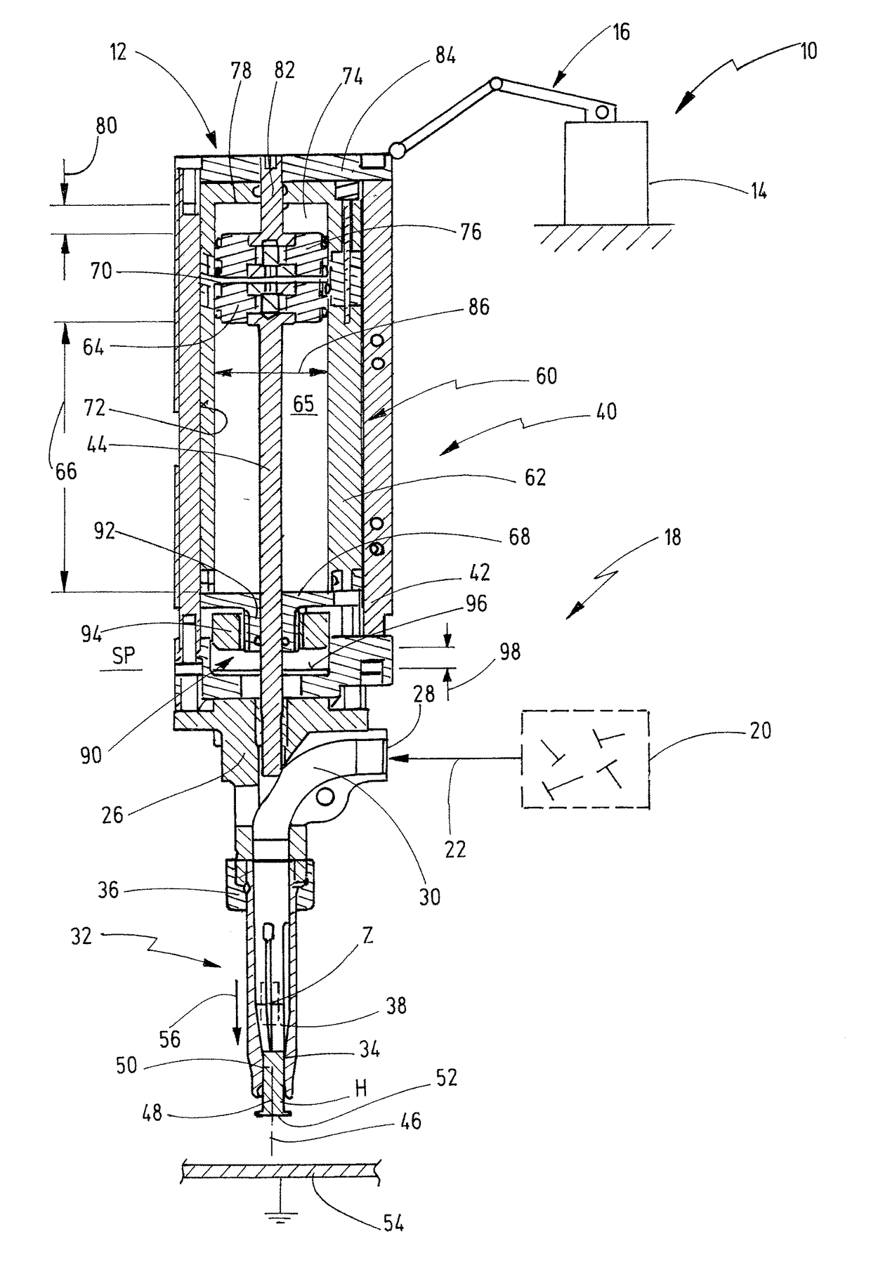
[0055]In FIG. 1, a joining system for joining joining elements onto workpieces is represented schematically and denoted in general terms by 10.

[0056]The joining system 10 has a joining head 12, which forms a joining apparatus. The joining head 12 is movable three-dimensionally in space, by way of example by means of a robot 14, wherein the joining head 12 is guided on one end of an arm 16 of the robot 14.

[0057]The joining system 10 further contains a feed device 18. The feed device 18 has a separating device 20, in which the joining elements are separated and are then conveyed via a feed system, for instance in the form of blow air, via a feed tube 22 to the joining head 12.

[0058]The joining head 12 contains a joining element receiver, which contains an inlet opening 28, via which separated joining elements are fed. The inlet opening 28 is connected via a feed channel 30 to a joining element holding device of the joining head 12. The joining element holding device 32 has a plurality...


PUM

PropertyMeasurementUnit
diameteraaaaaaaaaa
lengthaaaaaaaaaa
lengthaaaaaaaaaa

Abstract

Joining apparatus for joining joining elements onto workpieces, comprising a joining element holding device, which is configured to radially hold a joining element, and comprising a loading pin arrangement, which is configured to slide a joining element axially into a holding position in the joining element holding device, and / or to axially support the joining element during a joining process, wherein the loading pin arrangement has a loading pin, which is slidable by means of a loading pin actuator arrangement in the direction of the joining element holding device. The loading pin arrangement is here designed to variably establish a loading pin stroke of the loading pin between at least two stages, so that in a first stage the loading pin is displaceable less far in the direction of the joining element holding device than in a second stage.

Description

CROSS-REFERENCE TO RELATED APPLICATION[0001]This application claims priority from German Patent Application No. 102016112372.2, filed on Jul. 6, 2016, the disclosure of which is incorporated herein by reference.BACKGROUND OF THE INVENTION[0002]The present invention relates to a joining apparatus for joining joining elements onto workpieces, comprising a joining element holding device, which is configured to radially hold a joining element, and comprising a loading pin arrangement, which is configured to slide a joining element axially into a holding position in the joining element holding device, and / or to axially support the joining element during a joining process, wherein the loading pin arrangement has a loading pin, which is slidable by means of a loading pin actuator arrangement in the direction of the joining element holding device.[0003]In addition, the present invention relates to a method for loading a joining element into a joining element holding device of a joining appa...

Claims


Application Information

Patent Timeline
Patent Type & Authority Applications(United States)
IPC IPC(8): B23K9/20B23K37/04B23K1/005
CPCB23K9/201B23K1/005B23K37/04B23K9/206B23K9/20
Inventor SCHNEIDER, MICHAELIVO, HUBERTFISCHERMANNS, BETTINA
Owner NEWFREY
Why Eureka
Try Eureka