
Foam cushion cover

a foam cushion and cover technology, applied in the field of medical devices, can solve the problems of limited sealing ability of the cushion, low cost, and small gap between, and achieve the effect of high frequency welding

Active Publication Date: 2018-01-11
INTENSIVE THERAPEUTICS
View PDF2 Cites 5 Cited by
  • Summary
  • Abstract
  • Description
  • Claims
  • Application Information

AI Technical Summary

Benefits of technology

The patent describes a cushion that has two chambers, a panel, and a handle. The cushion can be inflated by removing a force from the first chamber, and the air can flow into the air pockets of the cushion through a hole in the panel. The cover of the cushion is made of elastic material and can be welded together using high frequency welding. The size of the cushion is designed to keep the air from escaping. The cushion can be in different shapes, such as wedge, rectangular, square, or semi-cylindrical. The first chamber and the second chamber can both have a thickness that remains closed to prevent the air from escaping. The cushion can also be made of translucent material. The technical effects of this patent are a more efficient and reliable inflated cushion with a controlled air pressure that can provide better shock absorption and comfort.

Problems solved by technology

Cover designs currently available offer some protection to the foam wedge inside the cover, but there are limits to how well the cushion can be sealed from contact with fluid and air contamination.
Sewing is fast and very cost effective, but the stitching creates small holes in the fabric and leaves very small gaps between the two pieces of fabric being joined.
Fluid and air can pass through these very small spaces and inspections for permeation are difficult to do and are rarely done in the care environment.
Sewn seams, zipper enclosures, and vents all present the same potential for air and fluid borne pathogens to enter into the foam cushion.
If the cushion becomes contaminated there is a high risk of spreading infection from one user to another within the healthcare environment.

Method used


Image

  • Foam cushion cover
  • Foam cushion cover
  • Foam cushion cover

Examples


Embodiment Construction

[0029]The embodiments herein and the various features and advantageous details thereof are explained more fully with reference to the non-limiting embodiments that are illustrated in the accompanying drawings and detailed in the following description. Descriptions of well-known components and processing techniques are omitted so as to not unnecessarily obscure the embodiments herein. The examples used herein are intended merely to facilitate an understanding of ways in which the embodiments herein may be practiced and to further enable those of skill in the art to practice the embodiments herein. Accordingly, the examples should not be construed as limiting the scope of the embodiments herein.

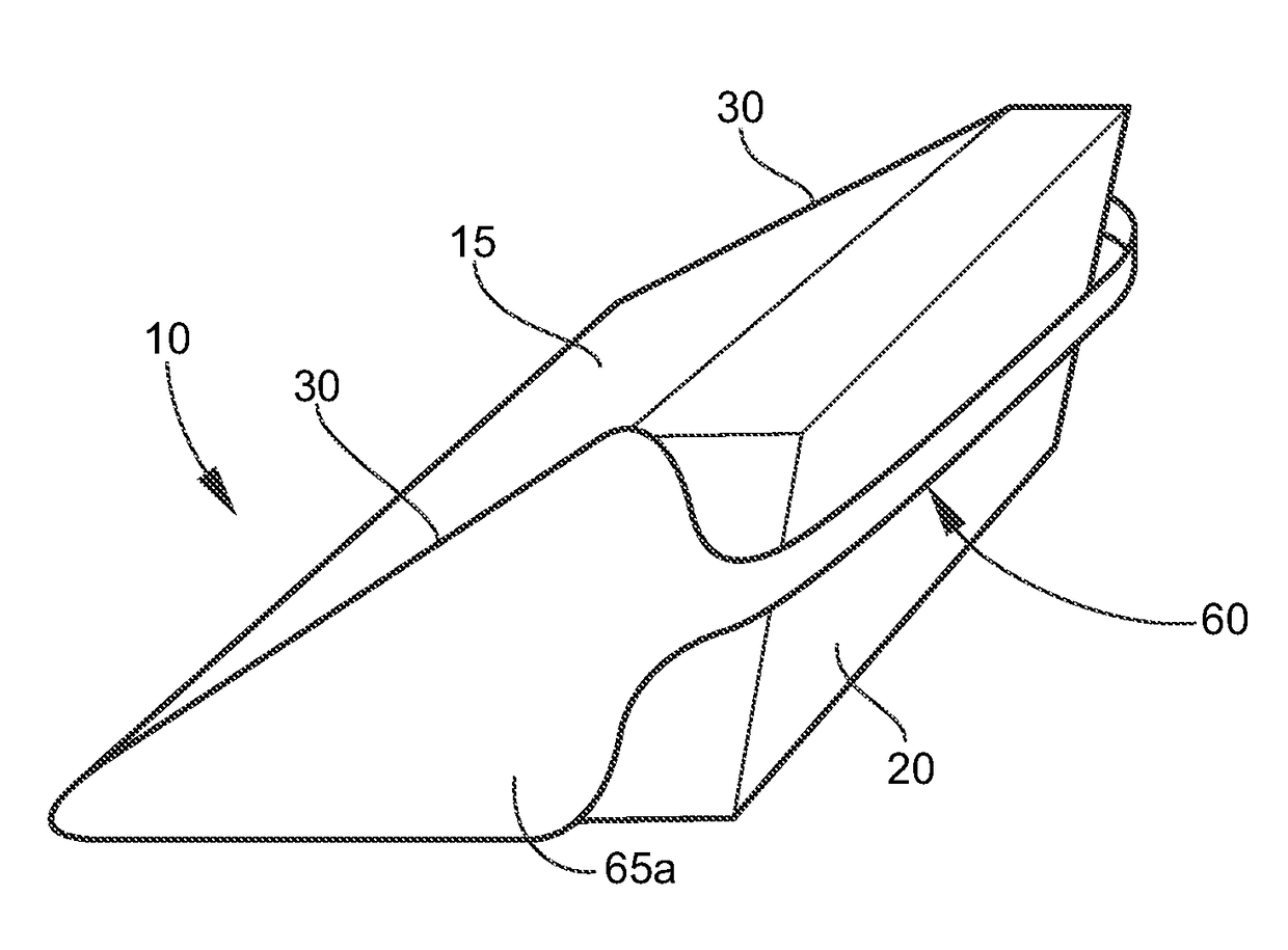
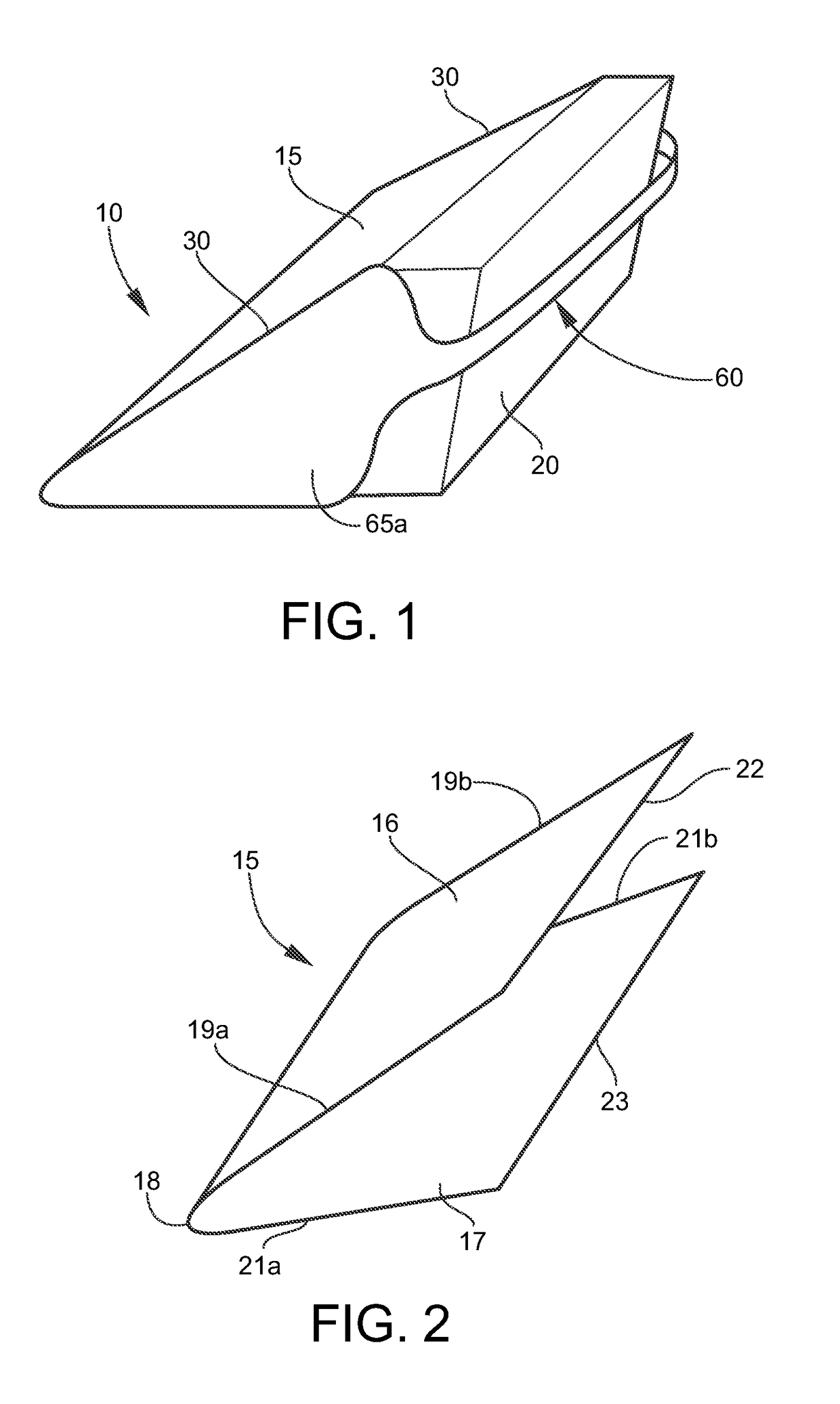
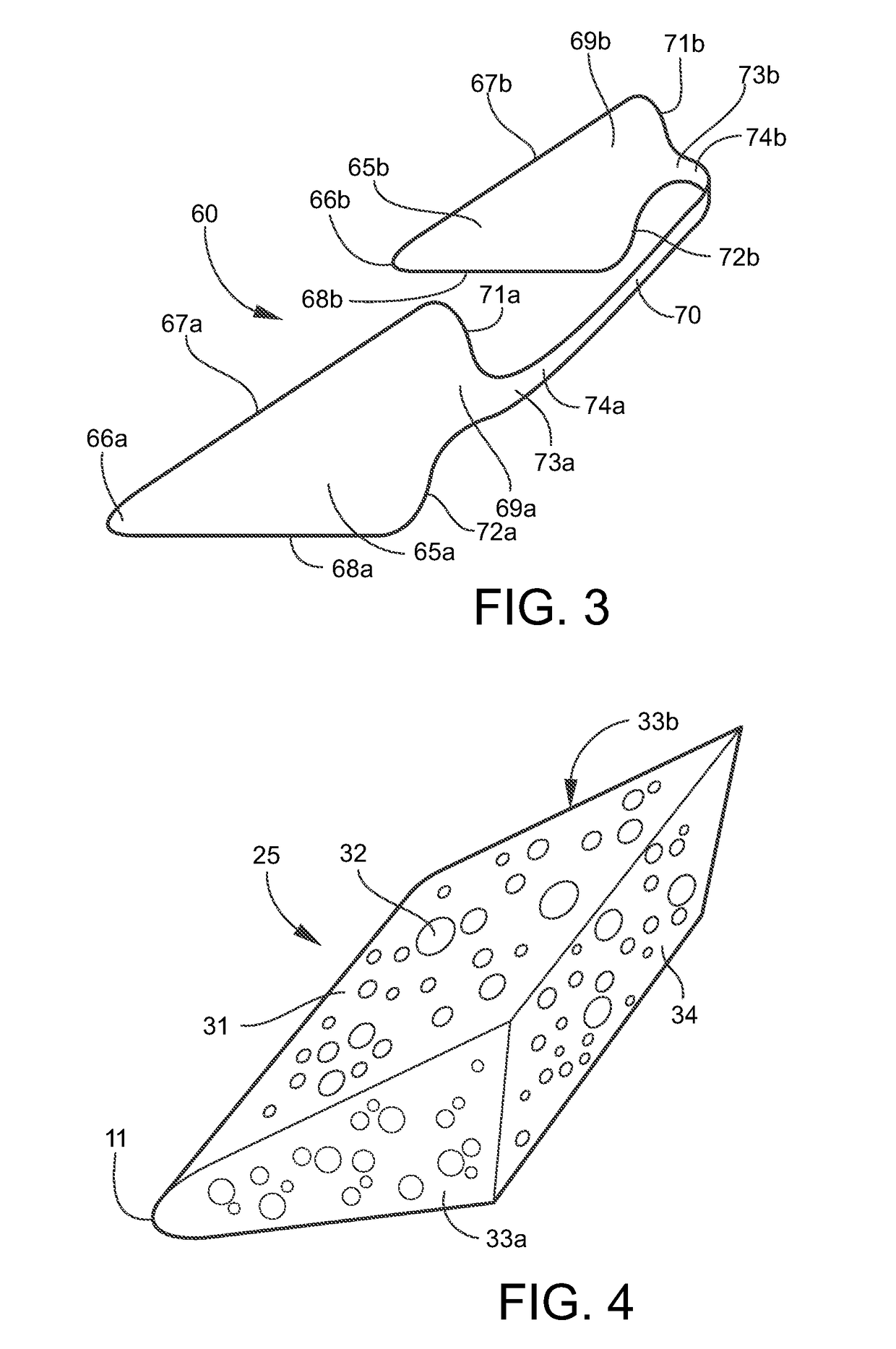
[0030]As mentioned, there is a need for a new type of foam cushion cover that reduces and / or eliminates the risk of cushion contamination and the spread of infectious pathogens. The embodiments herein provide a completely sealed and closed cover that encapsulates a foam cushion. Referring now t...


PUM


Abstract

A cushion cover includes a first chamber that includes at least one sheet, wherein the first chamber is configured to house a cushion that includes air pockets. A second chamber is sealed to the first chamber, wherein the second chamber includes a closed back end, a closed top, a closed bottom, a pair of closed sides, and an open front end. A panel, which includes at least one hole, is sealed to the first chamber and facing the open end of the second chamber. A handle is provided that includes a longitudinal strap adjoining a pair of side panels, wherein the pair of side panels are sealed to the first chamber, wherein upon a force being applied to the first chamber, air contained in the air pockets of the cushion flows through the at least one hole in the panel and into the second chamber without exiting the second chamber.

Description

BACKGROUNDTechnical Field[0001]The embodiments herein generally relate to medical devices, and more particularly to foam cushion covers.Description of the Related Art[0002]The proper positioning of an immobile patient in a health care setting is a very important task. Patients must be positioned at the proper angle of turn and any device used to assist with supporting the patient must stay in place for the duration of time prescribed by the clinical staff. One device used to support patients in the elevated side lying position is a polyurethane foam wedge cushion. Foam wedges are available in a wide variety of dimensions, densities, and colors. Foam wedges are also available in bare foam or with a cover, which is intended to make the cushion easy to clean and reuse from one patient to another. Cover designs currently available offer some protection to the foam wedge inside the cover, but there are limits to how well the cushion can be sealed from contact with fluid and air contamina...

Claims


Application Information

Patent Timeline
IPC IPC(8): A47G9/02A47C20/00A47G9/10A61G7/075
CPCA47G9/0253A47G9/10A47G2009/1018A61G7/0755A47C20/021A61G13/1245
Inventor DUDONIS, MATTHEW
Owner INTENSIVE THERAPEUTICS
Learn More