Medium discharging device and image reading apparatus
a technology of image reading and discharge device, which is applied in the direction of electrical apparatus, thin material handling, pictoral communication, etc., can solve the problems of easy entry, easy entry, and easy entry, and achieve the effect of easy entry and easy entry
- Summary
- Abstract
- Description
- Claims
- Application Information
AI Technical Summary
Benefits of technology
Problems solved by technology
Method used
Image

Examples
first embodiment
Regarding Image Reading Apparatus
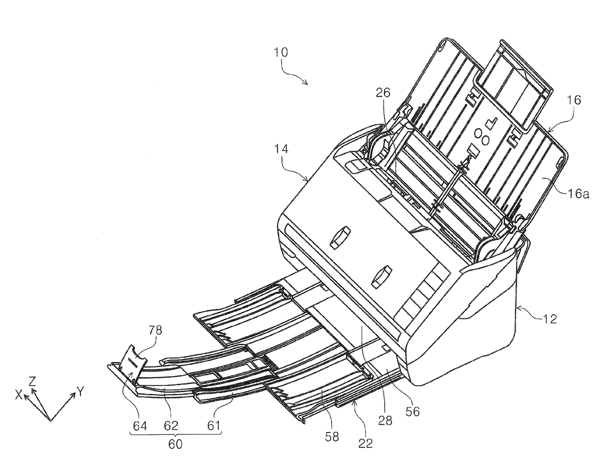
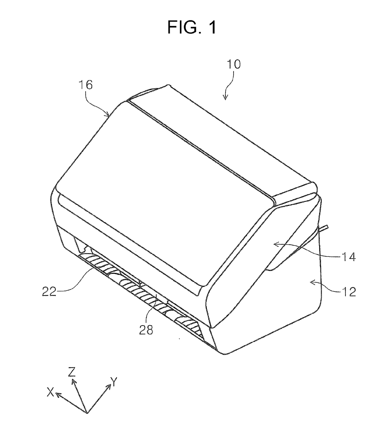
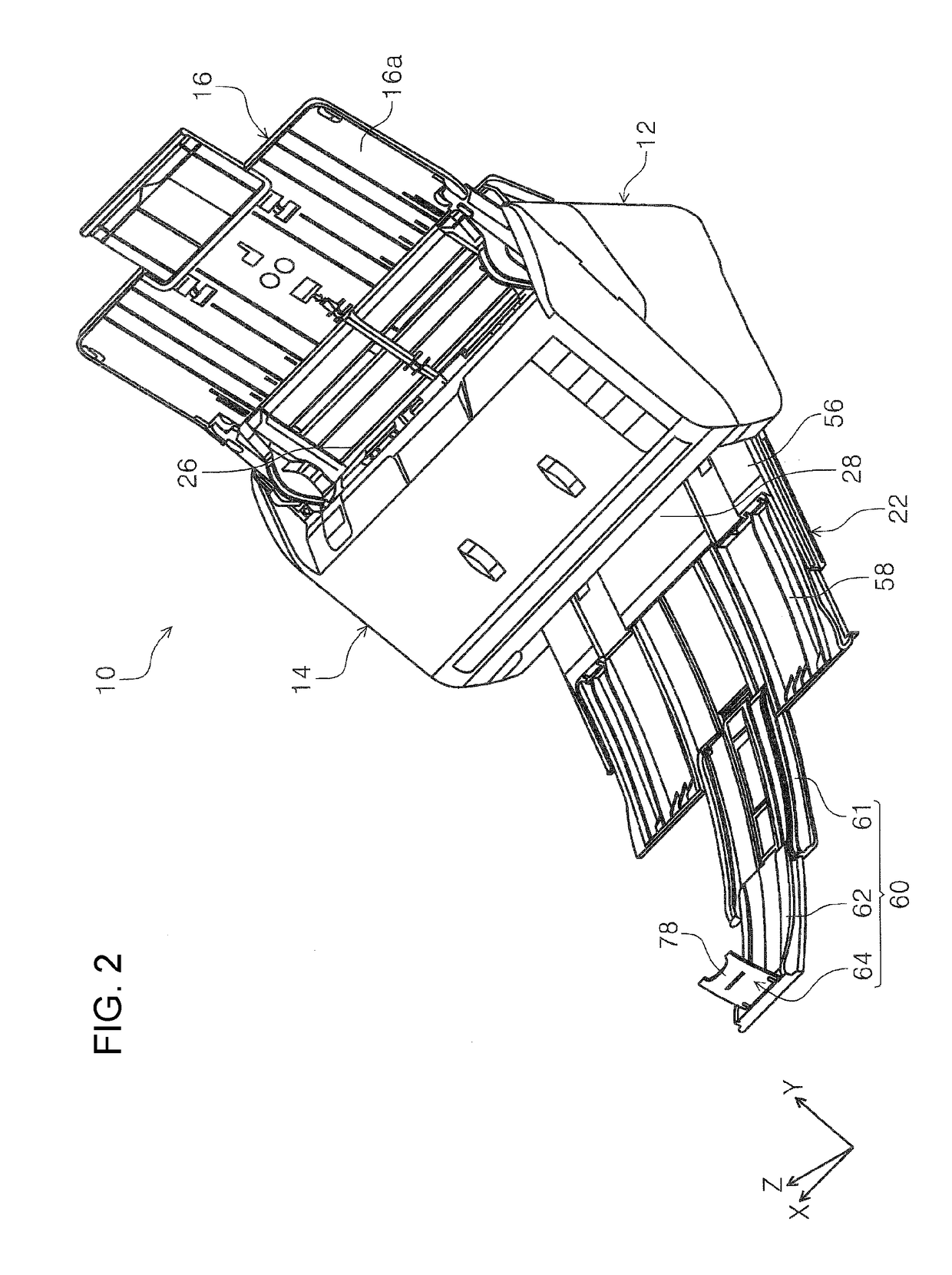
[0058]When referring to FIGS. 1 and 2, a scanner 10 as the “image reading apparatus” is provided with a lower unit 12, a higher unit 14, a cover unit 16, and a medium discharging device 18. The medium discharging device 18 is provided with a pair of discharging rollers 20 (refer to FIG. 3) and a medium receiving tray 22 (refer to FIG. 2) which will be described later. Exteriors of the lower unit 12 and the higher unit 14 configure a housing of the scanner 10.
[0059]The cover unit 16 is attached to a higher part on a rear face side of the lower unit 12 so as to rotate with respect to the lower unit 12. As illustrated in FIG. 1, the cover unit 16 obtains a non-feeding state in which a higher part of the higher unit 14 and a feeding port 26 (refer to FIG. 2) are covered, and a feeding state in which the cover unit rotates to a rear face side of the apparatus from the non-feeding state in FIG. 1, as illustrated in FIG. 2, and opens the feeding port 26. Wh...
modification example of first embodiment
[0102]It is set to a configuration in which the first protrusion portion 66 is provided with the plurality of first ribs 68 which extend in the apparatus depth direction, and the second protrusion portion 72 is provided with the plurality of second ribs 74 which extend in the apparatus width direction; however, a configuration in which the first protrusion portion 66 is provided with the plurality of second ribs 74, and the second protrusion portion 72 is provided with the plurality of first ribs 68 may be adopted, instead of the configuration.
second embodiment
[0103]A second embodiment which is a medium discharging device 88 will be described with reference to FIG. 22. FIG. 22 schematically illustrates the medium discharging device 88 in the second embodiment. The medium discharging device 88 in the second embodiment is different from the first embodiment in a point that an accommodated posture and a regulating posture of a stopper 90a of a stopper portion 90 is switched according to a length of a medium P which is discharged in a discharging direction. In addition, a medium receiving tray 92 is illustrated using two tray members by simplifying a configuration thereof in FIG. 22; however, it may be configured of two or more tray members, and may be configured of the base tray 56, the main extendeding unit 58, the first sub-extendeding unit 61, and the tip end extendeding portion 62, similarly to the first embodiment.
[0104]The medium discharging device 88 illustrated in FIG. 22 is provided with the medium receiving tray 92, and a switching...
PUM
| Property | Measurement | Unit |
|---|---|---|
| thickness | aaaaa | aaaaa |
| size | aaaaa | aaaaa |
| time | aaaaa | aaaaa |
Abstract
Description
Claims
Application Information
 - R&D
- Intellectual Property
- Life Sciences
- Materials
- Tech Scout
- Unparalleled Data Quality
- Higher Quality Content
- 60% Fewer Hallucinations
Browse by: Latest US Patents, China's latest patents, Technical Efficacy Thesaurus, Application Domain, Technology Topic, Popular Technical Reports.
© 2025 PatSnap. All rights reserved.Legal|Privacy policy|Modern Slavery Act Transparency Statement|Sitemap|About US| Contact US: help@patsnap.com