Robot, robot control apparatus and robot system
- Summary
- Abstract
- Description
- Claims
- Application Information
AI Technical Summary
Benefits of technology
Problems solved by technology
Method used
Image
Examples
first embodiment
[0140]As below, an embodiment of the invention will be explained with reference to the drawings.
[0141]First, a configuration of a robot system 1 will be explained.
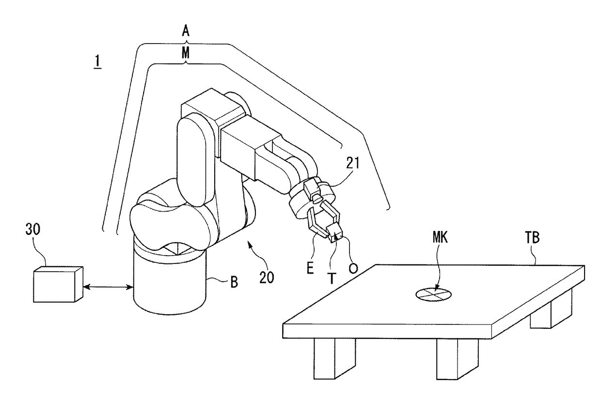
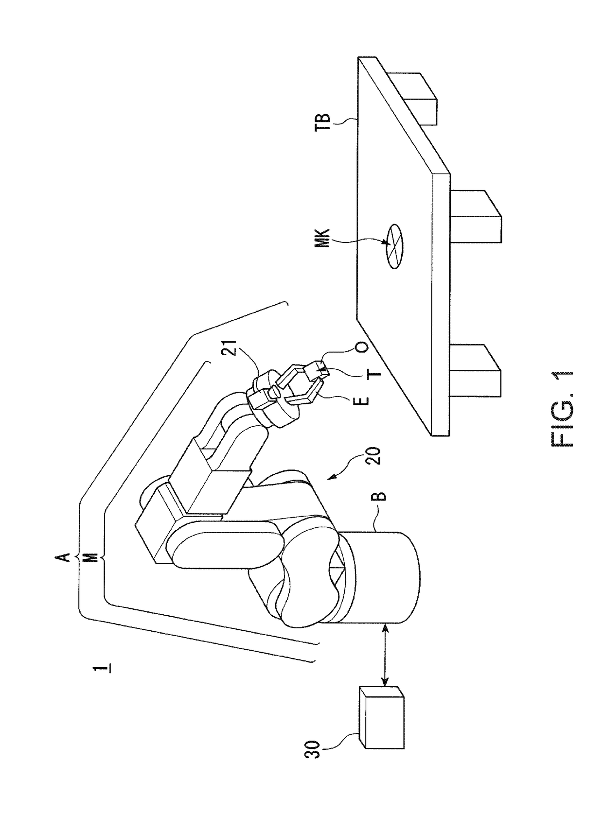
[0142]FIG. 1 shows an example of the configuration of the robot system 1 according to the embodiment. The robot system 1 includes a robot 20 and a robot control apparatus 30.
[0143]The robot 20 is a single-arm robot including an arm A and a support B that supports the arm A. The single-arm robot is a robot having a single arm like the arm A in the example. Note that the robot 20 may be a multi-arm robot in place of the single-arm robot. The multi-arm robot is a robot having two or more arms (e.g. two or more arms A). Of the multi-arm robots, a robot having two arms is also called a dual-arm robot. That is, the robot 20 may be a dual-arm robot having two arms or a multi-arm robot having three or more arms (e.g. three or more arms A). Alternatively, the robot 20 may be another robot such as a scal...
modified example 1 of embodiment
[0231]As below, referring to FIG. 15, Modified Example 1 of the embodiment will be explained.
[0232]The robot control apparatus 30 may be adapted, after calculating the position of the first marker MK at step S320 shown in FIG. 4, to store relative position information representing the relative position between the current position of the control point T (i.e., the position of the control point T when the position and the attitude of the control point T coincide with the second position and attitude) and the position of the first marker MK in the memory unit 32. In this case, the robot control apparatus 30 may detect (calculate) another marker provided in a different position from that of the first marker MK and second marker MK2 as a marker provided on the top surface of the worktable TB based on the relative position information.
[0233]Specifically, as shown in FIG. 15, the robot control apparatus 30 moves the position of the control point T with the attitude of the control point T ...
modified example 2 of embodiment
[0237]As below, Modified Example 2 of the embodiment will be explained. The robot control apparatus 30 may be adapted so that information representing relative position and attitude between the position and the attitude of the control point T and a position and an attitude of a coincidence point in the range that can be imaged by the imaging unit 21 may be stored in the memory unit 32 in advance. In this case, the robot control apparatus 30 allows the position and the attitude of the control point T to coincide with the first position and attitude in the processing at step S180 shown in FIG. 4, and then, calculates the position of the first marker MK based on the first position and attitude and the information stored in the memory unit 32 in advance. Thereby, the robot control apparatus 30 may shorten the time taken for the detection of the position of the first marker MK.
[0238]As described above, in the robot 20, a movable part (in the example, the arm A) performs actions based on ...
PUM
 Abstract
Description
Claims
Application Information
 - R&D
- Intellectual Property
- Life Sciences
- Materials
- Tech Scout
- Unparalleled Data Quality
- Higher Quality Content
- 60% Fewer Hallucinations
Browse by: Latest US Patents, China's latest patents, Technical Efficacy Thesaurus, Application Domain, Technology Topic, Popular Technical Reports.
© 2025 PatSnap. All rights reserved.Legal|Privacy policy|Modern Slavery Act Transparency Statement|Sitemap|About US| Contact US: help@patsnap.com


