Control device and robot system

a control device and robot technology, applied in the direction of electrical programme control, program-controlled manipulators, numerical control, etc., can solve the problems of difficult to achieve desired posture, inability to set the posture offset of the tool with respect to the robot arm, etc., to achieve easy and quick operation, easy and accurate tool setting

Active Publication Date: 2021-01-05
SEIKO EPSON CORP
View PDF15 Cites 6 Cited by
  • Summary
  • Abstract
  • Description
  • Claims
  • Application Information

AI Technical Summary

Benefits of technology

[0006]In this case, it is possible to easily and quickly perform an operation to input the information for obtaining the posture offset of the tool.
[0020]It is possible to easily and accurately set the tool in a desired posture according to a posture of the tool with respect to the robot arm included in the robot by obtaining the posture offset of the tool.

Problems solved by technology

However, in the method disclosed in JP-A-8-85083, since the offset is derived by positioning one point of the tool to the reference point, it is not possible to set a posture offset of the tool with respect to the robot arm even though it is possible to set the position offset of the tool with respect to the robot arm.
When the posture offset of the tool with respect to the robot arm is not set, since the posture of the tool with respect to the workpiece cannot be appropriately controlled, it is difficult to achieve a desired posture.

Method used


Image

  • Control device and robot system
  • Control device and robot system
  • Control device and robot system

Examples


first embodiment

Configuration of Robot Vision System (Robot System)

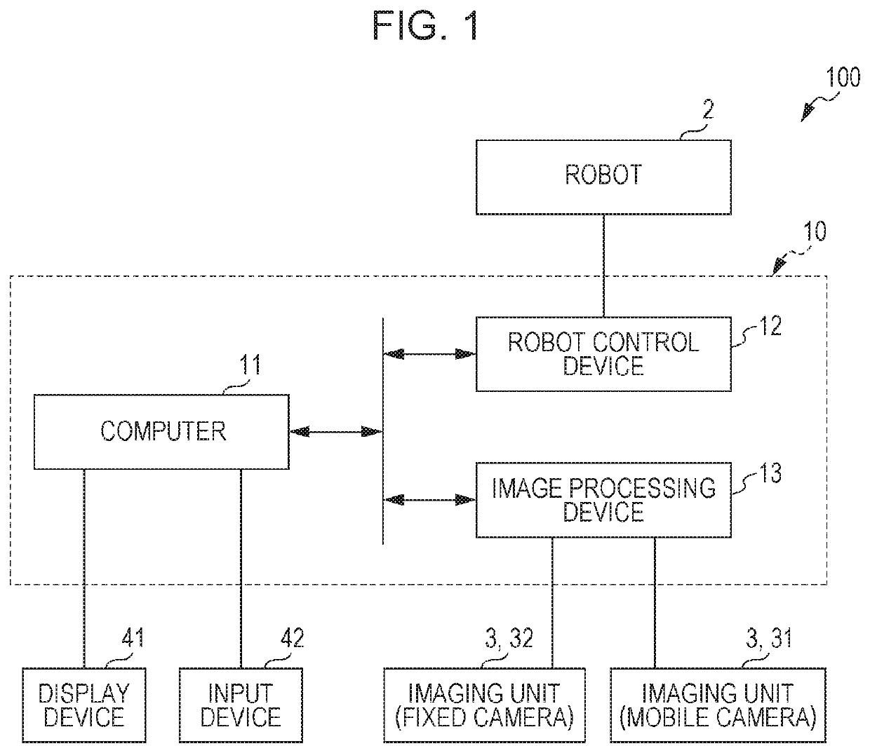
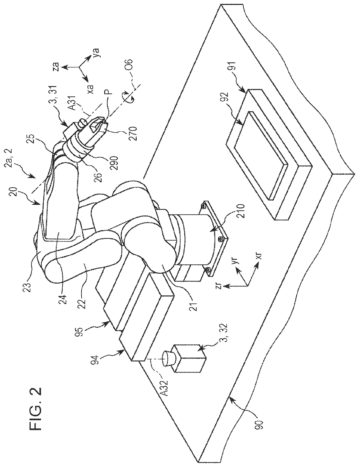
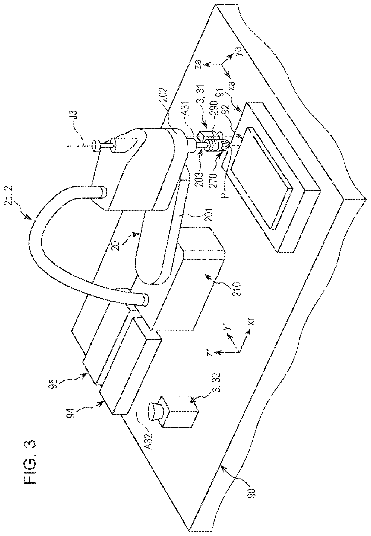
[0099]FIG. 1 is a network diagram of a robot vision system according to a first embodiment of the invention. FIG. 2 is a perspective view illustrating an example of a robot included in the robot vision system illustrated in FIG. 1. FIG. 3 is a perspective view illustrating an example of a robot included in the robot vision system illustrated in FIG. 1. FIG. 4 is a system configuration diagram of the robot illustrated in FIG. 2 or FIG. 3. FIG. 5 is a system configuration diagram of a computer included in a robot system illustrated in FIG. 1. FIG. 6 is a system configuration diagram of a robot control device included in the robot system illustrated in FIG. 1. FIG. 7 is a system configuration diagram of an image processing device included in the robot system illustrated in FIG. 1.

[0100]In the following description, the upper side of FIGS. 2 and 3 is referred to as “upper”, and the lower side thereof is referred to as “lower” for the co...

second embodiment

[0501]FIGS. 56 and 57 are perspective views illustrating examples of robots, examples of tools attached on robot arms, and examples of teaching tools included in a robot vision system according to a second embodiment of the invention, respectively. FIG. 58 is a flow diagram illustrating a flow of a tool setting of the robot vision system according to the second embodiment of the invention. FIGS. 59 to 70 are posture setting guide screens of the robot vision system according to the second embodiment of the invention, respectively. FIGS. 71 to 76 are diagrams for describing the tool setting of the robot vision system according to the second embodiment of the invention.

[0502]In the following description, the upper side of FIGS. 56 to 76 is referred to as “upper”, and the lower side thereof is referred to as “lower” for the convenience of description. In FIGS. 71 to 76, a base end side of the tool is omitted.

[0503]Hereinafter, the second embodiment will be described, but differences fro...


PUM


Abstract

A control device that controls driving of a robot, the control device includes a processor that is configured to execute computer-executable instructions so as to control a robot, wherein the processor is configured to: display a posture setting guide for guiding information input for obtaining a posture offset of a tool provided on the robot, on a display; and control the driving of the robot based on the posture offset of the tool.

Description

BACKGROUND1. Technical Field[0001]The present invention relates to a control device, and a robot system.2. Related Art[0002]In the related art, processing of setting an offset of a tool with respect to a robot arm is performed before processing a workpiece using the tool installed on the robot arm. JP-A-8-85083 discloses a method of running an operation for positioning the tool installed on the robot arm to a reference point of a real space a plurality of times while changing a posture of the robot arm, and deriving the offset of the tool with respect to the robot arm based on the result thereof.[0003]When the workpiece is processed by the tool, the tool is required to bring into contact with or close to the workpiece in an appropriate posture. However, in the method disclosed in JP-A-8-85083, since the offset is derived by positioning one point of the tool to the reference point, it is not possible to set a posture offset of the tool with respect to the robot arm even though it is ...

Claims


Application Information

Patent Timeline
Patent Type & Authority Patents(United States)
IPC IPC(8): G05B19/04G05B19/18B25J9/16B25J13/06
CPCB25J9/1692B25J9/1671B25J9/1687B25J9/1697B25J13/06Y10S901/09B25J9/161B25J9/1612B25J13/00
Inventor MATSUURA, KENJIYAMAUCHI, MEGURU
Owner SEIKO EPSON CORP
Why Eureka
Try Eureka