Wiper system and wiper system control method

a technology of wiper system and control method, which is applied in the field of wipers to achieve the effects of relaxing the work accuracy of attaching the blade, reducing the errors in the position information of the blade, and improving the control accuracy and wiping performan

Active Publication Date: 2020-01-28
MITSUBA CORP
View PDF18 Cites 1 Cited by
  • Summary
  • Abstract
  • Description
  • Claims
  • Application Information

AI Technical Summary

Benefits of technology

[0013]According to the wiper system and the wiper system control method of the present invention, the wiper system performs operation control on the electric motor, which drives and rotates the pivot shaft to which the wiper arm is fixed, based on the position information about the wiper blade, wherein the learning mode in which the position of the wiper blade is learned to correct the position information is executed after the wiper arm is attached to the pivot shaft. The position information about the wiper blade can thus be changed on the actually-installed wiping surface. This can reduce errors in the blade position information due to variations in the attached position of the wiper blade, and improve control accuracy and wiping performance.
[0014]Since the position information about the wiper blade is learned after the wiper arm is mounted, the work accuracy in attaching the blade is relaxed. This facilitates the setting of the arm & blade, and reduces the work burden on the worker. Since the arm & blade are easily and accurately set, reassembling work for angle correction is not needed. This reduces disposal loss due to attachment failures, and cut manufacturing costs.

Problems solved by technology

Since the position of the wiper arm is designed on the basis of theoretical values calculated in advance, the position of the wiper blade varies vehicle by vehicle due to dimensional errors, rigidity, and the like of the wiper arm, the wiper blade, and the body.
In particular, when an assembly of a wiper arm and a wiper blade (hereinafter, abbreviated as arm & blade) is mounted on the vehicle body, the wiper arm is attached by using a predetermined jig because the assembly is susceptible to deflection of the arm or the blade.

Method used


Image

  • Wiper system and wiper system control method
  • Wiper system and wiper system control method
  • Wiper system and wiper system control method

Examples


Embodiment Construction

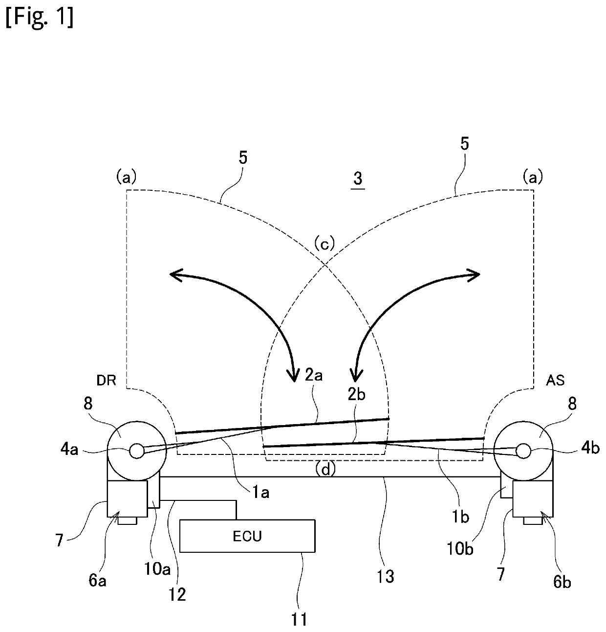
[0019]An embodiment of the present invention will be described in detail below with reference to the accompanying drawings. An object of the following embodiment is to facilitate work for attaching an arm & blade and improve accuracy of the attached position for reduced disposal loss. FIG. 1 is an explanatory diagram illustrating an overall configuration of a wiper system which is an embodiment of the present invention. The wiper system of FIG. 1 has an apparatus configuration of opposite wiping type. A wiper arm 1a on a driver's seat side (DR side) and a wiper arm 1b on an assistant driver's seat side (AS side) (hereinafter, abbreviated as arms 1a and 1b) are arranged to be opposed to each other. Wiper blades 2a and 2b (hereinafter, abbreviated as blades 2a and 2b) are attached to the arms 1a and 1b, respectively. The blades 2a and 2b are elastically contacted with a windshield (wiping surface) 3 by unillustrated spring members and the like arranged inside the arms 1a and 1b.

[0020...


PUM


Abstract

A wiper system performs operation control on wiper driving electric motors and based on position information about wiper blades and attached to pivot shafts, wherein a learning mode in which a position of the wiper blades is learned to correct blade position information is executed after the wiper blades are attached to the pivot shafts, respectively. In the learning mode, the wiper blades are moved to a prescribed position such as a lower retracted position, and that the wiper blades are located in the prescribed position is detected by such means as a sensor, a video image, and contact with a jig. If the wiper blades are detected to be in the prescribed position, the blade position information is corrected to a value corresponding to the position.

Description

TECHNICAL FIELD[0001]The present invention relates to a technique for controlling a vehicle wiper system mounted on an automobile and the like, and more particularly to initial setting processing when attaching a wiper apparatus to a vehicle.BACKGROUND ART[0002]Vehicles such as an automobile are equipped with wiper apparatuses for wiping off rain water adhering to a windshield (front windshield) and splashes from front vehicles for the purpose of ensuring the driver's field of view in cases of rainy weather. A wiper apparatus includes a wiper arm which is controlled to oscillate by a wiper driving device. A wiper blade which comes into contact with a windshield is attached to the end of the wiper arm. A pivot shaft which is driven to rotate by a wiper motor is arranged on the body side of the vehicle. The wiper arm is attached to the pivot shaft, and oscillates at a preset control angle according to rotation of the motor.[0003]In attaching a wiper arm to a pivot shaft, the wiper arm...

Claims


Application Information

Patent Timeline
Patent Type & Authority Patents(United States)
IPC IPC(8): B60S1/08B60S1/04
CPCB60S1/0461B60S1/0807B60S1/08B60S1/0452B60S1/0469
Inventor KOIKE, TETSUYAHIRATA, KENSHIMIZU, KENGO
Owner MITSUBA CORP
Why Eureka
Try Eureka