Hose puller and method

a technology of hoses and pullers, which is applied in the direction of packaging, liquid transfer devices, manufacturing tools, etc., can solve the problems of causing significant torque at the lower back, heavy nozzles and hoses, and causing significant force at the shoulder, lower back and/or other locations on the body, so as to minimize or reduce the risk of unnecessarily twisting the lower back. , the effect of avoiding unnecessary twisting

Active Publication Date: 2018-01-04
OZOLS PETER
View PDF1 Cites 0 Cited by
  • Summary
  • Abstract
  • Description
  • Claims
  • Application Information

AI Technical Summary

Benefits of technology

The present invention is related to a device and method for holding and pulling a hose and nozzle assembly. The device has a nozzle with a groove or recess and a lock with a narrower width that securely fits into the groove or recess on the nozzle body. The advantages of the device include avoiding shoulder pain, twisting damage, and unintentional dispensing or spilling of liquids during pulling. The device allows for symmetrical gripping and reduces the risk of unintentional twisting while pulling the hose and nozzle assembly. The invention also ensures that the dispensing end of the nozzle is facing upward, away from contact during pulling to prevent accidents.

Problems solved by technology

One of the drawbacks of pulling a hose in this manner, is that the nozzle and hose, which can be filled with fuel, are heavy.
In addition, when the weight of the nozzle and hose is supported over the shoulder, it can create significant forces at the shoulder, lower back and / or at other locations on the body.
For example, if the workman twists or rotates his or her upper body with the nozzle and hose supported over the shoulder, the weight of the nozzle and hose can create a significant torque at the lower back.
Such forces can damage the lower back.
In addition, the weight of the nozzle and hose assembly can damage the shoulder or other portions of the upper body.
Another drawback is that when held in front of the chest and pulled in that position, the nozzle can leak fuel oil onto the workman or onto his or her clothes.

Method used


Image

  • Hose puller and method
  • Hose puller and method
  • Hose puller and method

Examples


Embodiment Construction

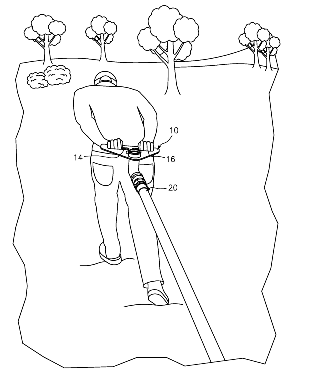
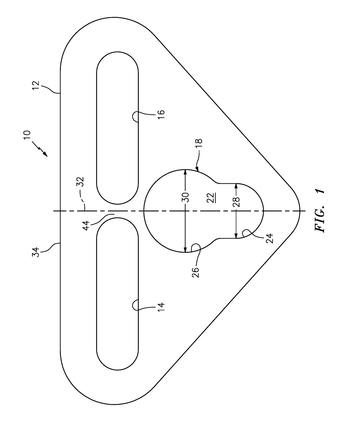
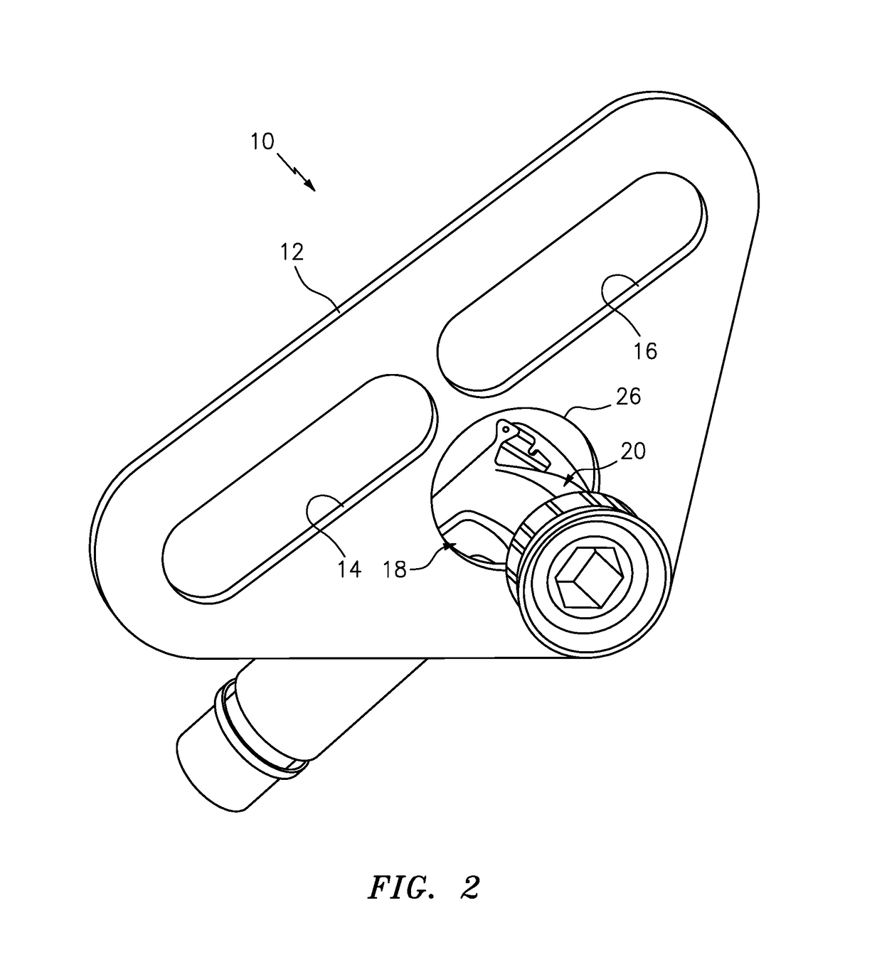
[0028]In FIGS. 1 through 6, a device for pulling a hose and nozzle assembly is indicated generally by the reference numeral 10. The device 10 comprises a plate 12 defining a first laterally-extending aperture 14 forming a first laterally-extending grip, and a second laterally-extending aperture 16 forming a second laterally-extending grip. A lock 18 is spaced below the first and second grips 14 and 16, respectively, and is releasably engageable with the hose and / or nozzle of a hose and nozzle assembly 20. As shown typically in FIG. 6, the first laterally-extending grip 14 is manually engageable by a first hand, such as a left hand, to grip the device 10, and the second laterally-extending grip 16 is manually engageable by a second hand, such as a right hand, to grip the device, and pull the device while gripping it, including in a position behind the back, and thereby pull the hose and nozzle assembly 20 secured to the device. As shown typically in FIGS. 2-4, the lock 18 and / or hose...


PUM


Abstract

A device for pulling a hose and nozzle assembly comprises a laterally-extending grip manually engageable by one or both hands to grip the device and pull a hose and nozzle assembly attached thereto. A lock is spaced below the grip and is releasably engageable with the hose and nozzle assembly. The lock or hose and nozzle assembly is movable relative to the other between (i) a locked position, wherein the hose and nozzle assembly is secured by the lock to the device and the hose and nozzle assembly is supported therefrom, and (ii) an unlocked position, wherein the hose and nozzle assembly is released from the lock and detached from the device. In the locked position, the laterally-extending grip is manually engageable to pull the device, including in a position behind the back, and thereby pull the hose and nozzle assembly secured thereto.

Description

CROSS-REFERENCE TO PRIORITY APPLICATION[0001]This patent application claims benefit under 35 U.S.C. §119 to U.S. provisional application No. 62 / 356,123, filed Jun. 29, 2016, entitled “Hose Puller and Method,” which is expressly incorporated by reference as part of the present disclosure.FIELD OF THE INVENTION[0002]The present invention relates to pulling hoses and to devices for pulling hoses, such as fuel oil hoses, and more particularly, relates to devices that are attachable to fuel oil hose and nozzle assemblies to pull the hoses and to methods of pulling hoses, such as from behind the back.BACKGROUND INFORMATION[0003]A typical fuel oil hose, such as home heating oil hose, includes a nozzle and hose assembly, and is rotatably mounted on a fuel oil truck, such as a tanker containing home heating oil. In order to fill a home or other heating oil fuel tank, a driver or other workman holds the nozzle-end of the hose, and pulls the hose from the truck to the inlet of the fuel tank. T...

Claims


Application Information

Patent Timeline
Patent Type & Authority Applications(United States)
IPC IPC(8): B67D7/40B65G7/12B25B9/02B25B9/00B67D7/00
CPCB67D7/406B25B9/02B25B9/00B67D7/00B65G7/12B67D7/38
Inventor OZOLS, PETER D.
Owner OZOLS PETER
Why Eureka
Try Eureka