Advanced warning indicator for emergency medical devices

a warning indicator and advanced technology, applied in the field of emergency medical devices, can solve the problems of a medical device likely to fail operationally, no advanced warning of a pending failure of a ready-for-use emergency medical device, and improperly functioning emergency medical device out of service, so as to shorten the reliable life of the operational component(s)

Active Publication Date: 2018-01-04
KONINKLJIJKE PHILIPS NV
View PDF11 Cites 3 Cited by
  • Summary
  • Abstract
  • Description
  • Claims
  • Application Information

AI Technical Summary

Benefits of technology

[0015]One form of the present invention is an emergency medical device (e.g., an external defibrillator/monitor) employing an emergency medical subsystem for executing an emergency medical procedure (e.g., a monitoring subsystem or a therapy subsystem), and an emergency medical controller for controlling an activation of the emergency medical subsystem. The subsystem includes one or more operational components. In operation, the controller conditionally actuates a device readiness indicator (e.g., auditory or visual) indicative

Problems solved by technology

A limitation of this scheme is that there is no advanced warning of a pending failure of a ready-for-use emergency medical device.
Working with only this Boolean indicator, designers of emergency medical devices are constrained to characterize marginal test results as failures, with the possible implication of a false failure that needlessly takes a properly fun

Method used


Image

  • Advanced warning indicator for emergency medical devices
  • Advanced warning indicator for emergency medical devices
  • Advanced warning indicator for emergency medical devices

Examples


Embodiment Construction

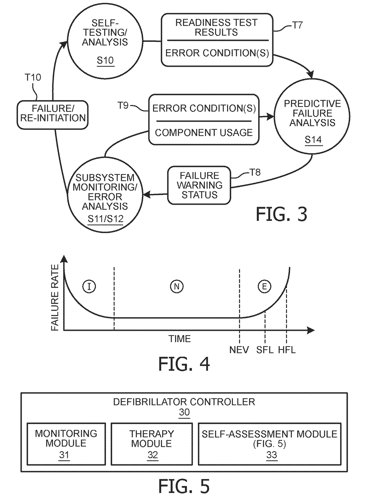
[0028]To facilitate an understanding of the present invention, exemplary embodiments of the present invention will be provided herein directed to an implementation of a predictive failure analysis by an emergency medical controller of the present invention.

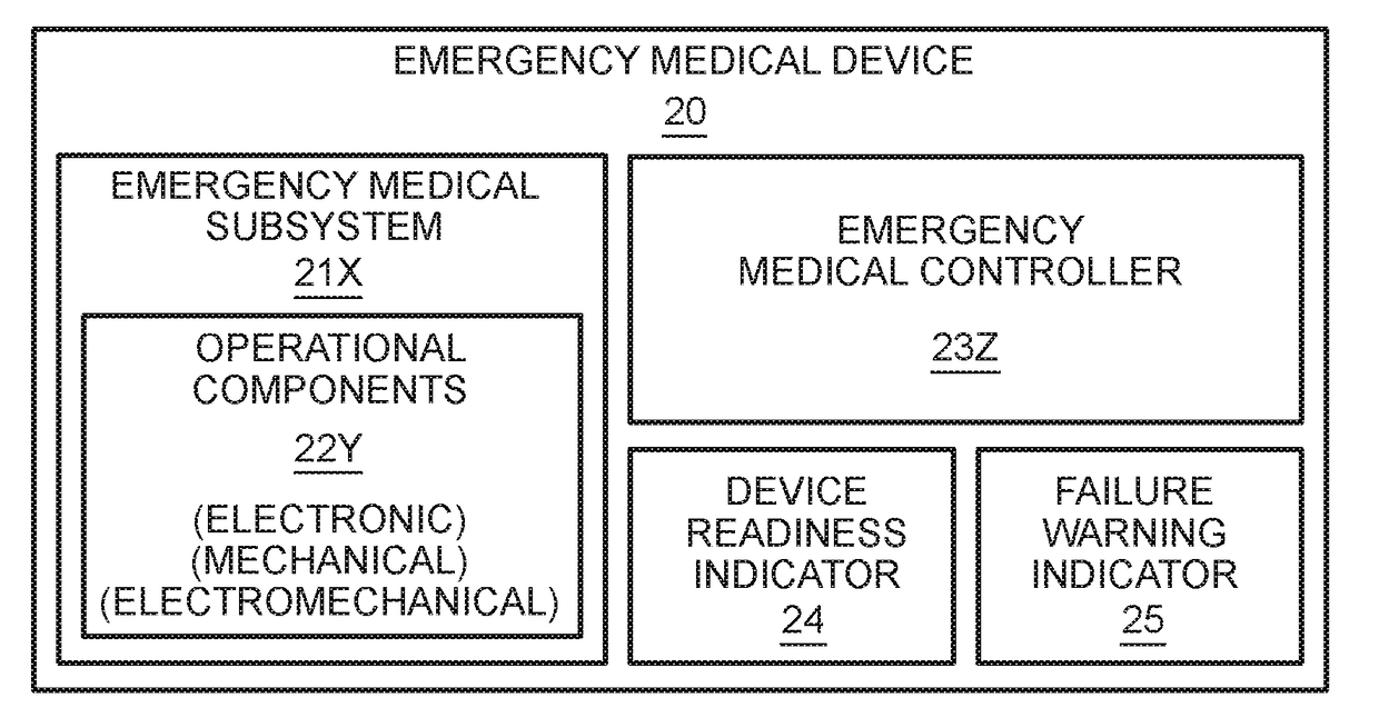
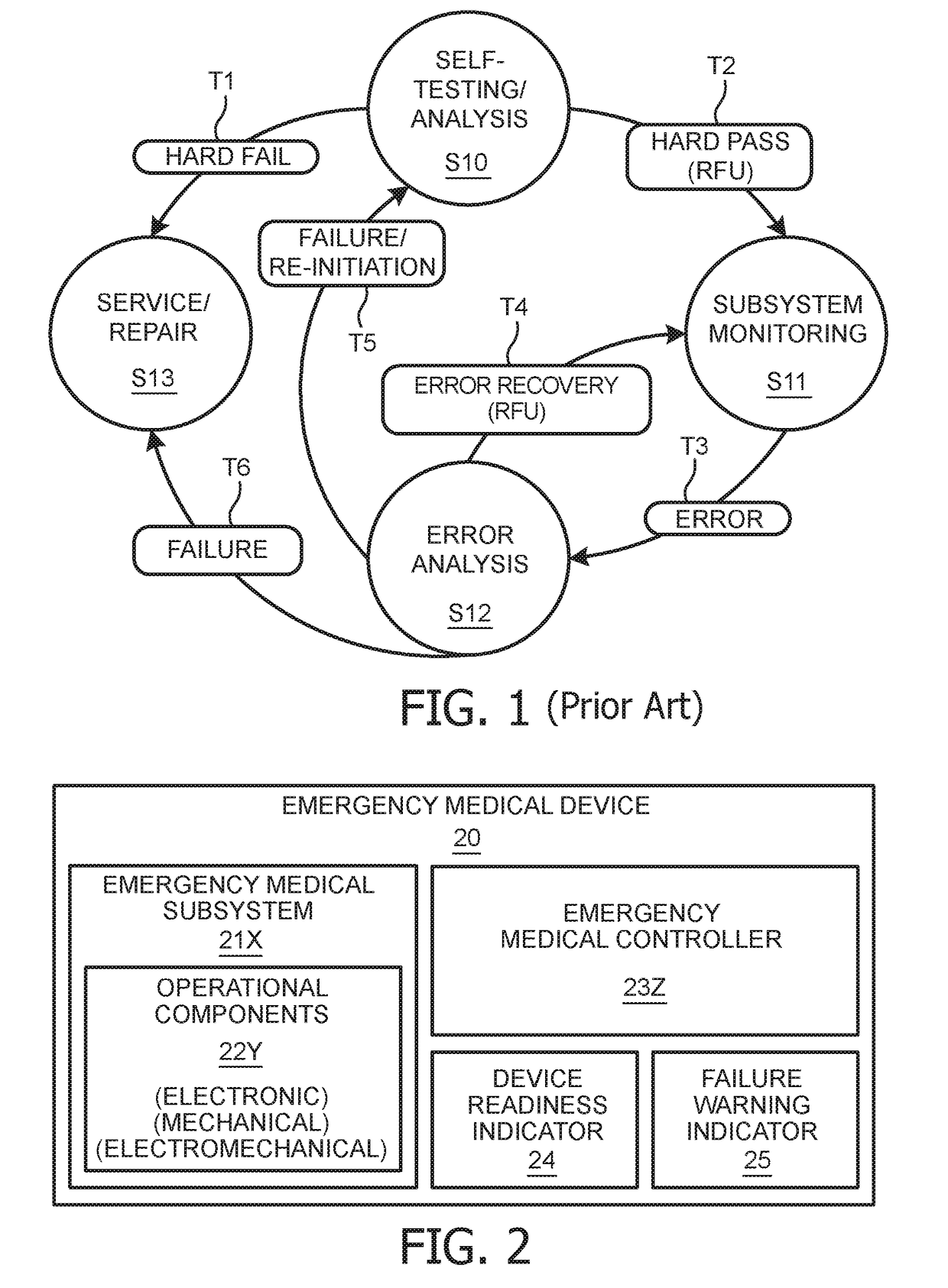
[0029]Referring to FIG. 2, an emergency medical device 20 (e.g., an external defibrillator / monitor) employs an X number of emergency medical subsystems 21, X≧1 for executing an X number of emergency medical procedures. Examples of subsystems 21 include, but are not limited to:

[0030](1) an electrocardiogram (“ECG”) monitoring subsystem for generating and displaying an ECG of a patient connected via leads to device 20; and

[0031](2) a therapy subsystem for applying a defibrillation shock, a synchronized cardioversion or a transcutaneous pacing to a patient connected / coupled via leads / pads / paddles to device 20.

[0032]Each subsystem 21 employs a Y number of operational components structurally assembled to execute the corresponding emerg...


PUM


Abstract

An emergency medical device (20) (e.g., an external defibrillator/monitor) employing an emergency medical subsystem (21) for executing an emergency medical procedure (e.g., a monitoring subsystem (21) and a therapy subsystem (21)), and an emergency medical controller (23) for controlling an activation of the emergency medical subsystem (21). The subsystem (21) includes one or more operational components (22). In operation, the controller (23) conditionally actuates a device readiness indicator (24) (e.g., auditory or visual) indicative of an operational readiness of the operational component(s) (22), and conditionally actuates a failure warning indicator (25) (e.g., auditory or visual) indicative of a pending failure of the operational readiness of the operational component(s) (22). The failure warning indicator (25) may be actuated based on a predictive failure analysis of a premature degradation of the operational component(s) (22), a repeated occurrence of error conditions of the operational component(s) (22) (particularly recoverable error conditions), and a shortened reliable life of the operational component(s) (22).

Description

FIELD OF THE INVENTION[0001]The present invention generally relates to emergency medical devices (e.g., an external defibrillator / monitor). The present invention specifically relates to an advanced warning of a pending failure of an operationally ready emergency medical device.BACKGROUND OF THE INVENTION[0002]An emergency medical device (e.g., an external defibrillator / monitor) is used in emergency lifesaving situations where seconds count. For example, when someone succumbs to a sudden cardiac arrest, the likelihood of resuscitation decreases each minute thereafter. Thus, it is critically important for the emergency medical device to be ready for use when it is needed. Consequently, device readiness indicators are commonly used in emergency medical devices to inform the user whether or not the emergency medical device is ready-for-use.[0003]In practice, many emergency medical devices are turned-off most of the time and standard protocol mandates a periodic assessment of whether the...

Claims


Application Information

Patent Timeline
IPC IPC(8): A61N1/39G06F19/00G16Z99/00
CPCA61N1/3925A61N1/3904A61N1/3993G06F19/3412G16H40/40A61N1/39A61B2560/0276G16H40/63G16Z99/00G01R31/2836G16H20/40
Inventor DELISLE, NORMAN MAURICEHUNT, DAVID K
Owner KONINKLJIJKE PHILIPS NV
Why Eureka
Try Eureka