
Wire for electric fencing lines and electric fencing lines made from such wires

a technology of electric fencing and wires, which is applied in the direction of conductive materials, metal/alloy conductors, conductors, etc., can solve the problems of difficult lifetime of electric fencing lines and low internal electrical resistance of electric fencing lines, and achieve the effects of improving the tensile strength of coated carbon steel wires, enhancing adhesion, and increasing the conductivity of electric fencing lines

Inactive Publication Date: 2017-12-28
NV BEKAERT SA
View PDF4 Cites 0 Cited by
  • Summary
  • Abstract
  • Description
  • Claims
  • Application Information

AI Technical Summary

Benefits of technology

The present invention provides an electric fencing line with low-cost, long-lasting carbon steel wires that have improved electrical conductivity and corrosion resistance. The carbon steel wire is coated with a zinc aluminium alloy or zinc aluminium magnesium alloy coating that can provide better corrosion resistance than traditional zinc coating. The coating is applied through hot dipping or electro-plating and is thick enough to provide good corrosion resistance. The coated carbon steel wire has a higher conductivity than copper wire, which is commonly used for electric fencing lines, and is a cheaper alternative. The coating is effective in preventing corrosion and provides better conductivity and corrosion resistance than traditional zinc coating. The carbon steel wire used for the electric fencing line has a diameter of 0.1-1.0 mm and is preferably redrawn to improve its strength and adhesion to the coating. The plastic material used for the electric fencing line can be a plastic material with good mechanical properties, such as polyethylene or polyethylene with good electrical conductivity. The specific electrical resistance of the coated carbon steel wire is in the range of 4×10⁻⁸ to 5.0×10⁻⁷ Ω·m.

Problems solved by technology

Therefore, such electric fencing lines must have a relatively low internal electrical resistance.
However, the lifetime of the electric fencing lines remains a challenge.

Method used


Image

  • Wire for electric fencing lines and electric fencing lines made from such wires
  • Wire for electric fencing lines and electric fencing lines made from such wires

Examples


Embodiment Construction

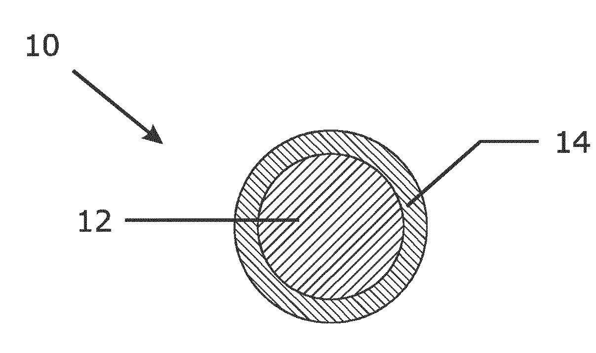
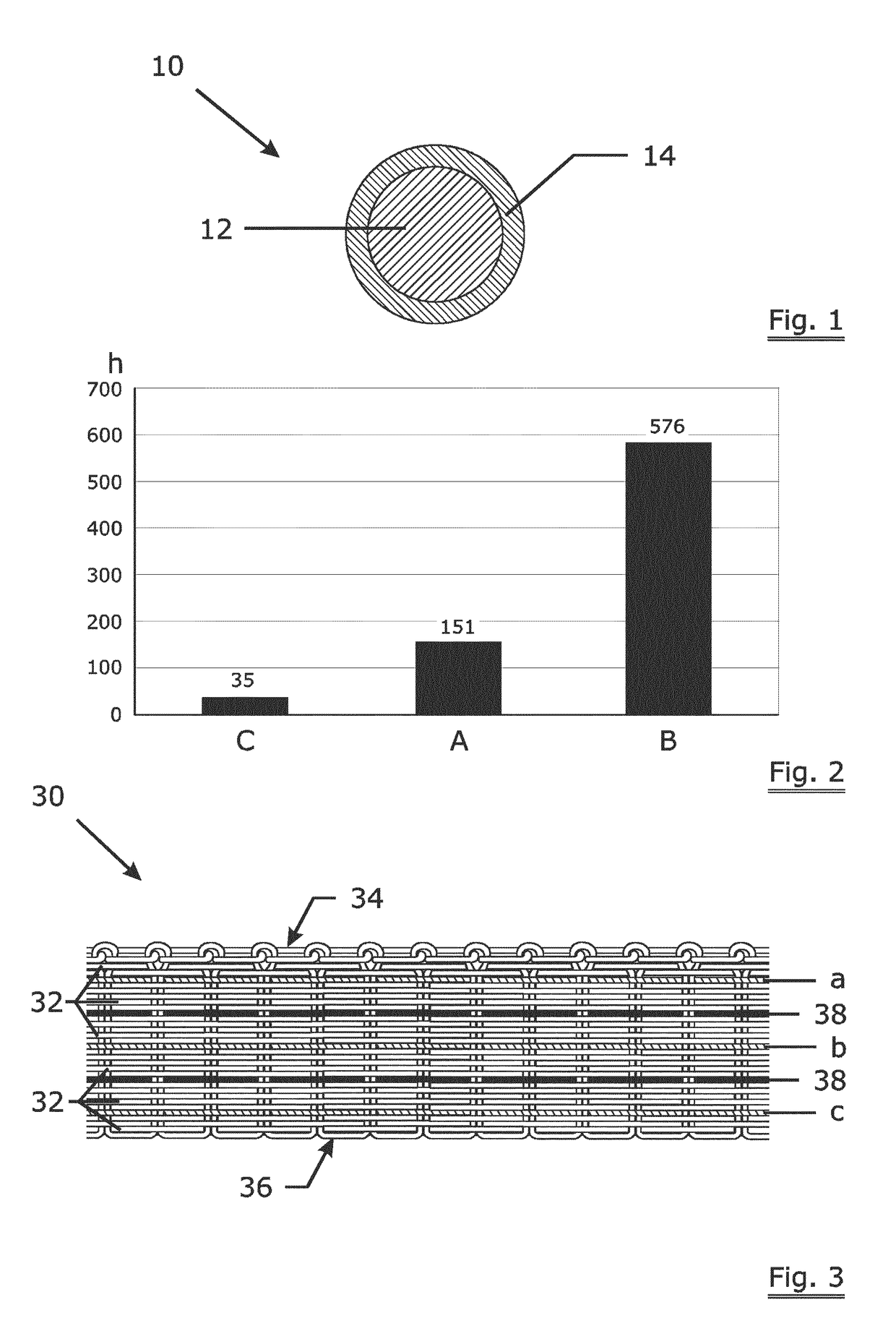
[0022]FIG. 1 shows a schematic view of a coated wire 10 according to the present invention. The coated wire 10 has a carbon steel core 12 and a zinc aluminium alloy coating 14. As an example, a low carbon steel wire having a carbon content of maximum 0.03 wt % and a silicon content of maximum 0.03 wt % was first coated with zinc aluminium alloy by hot dipping. Wire A is coated with zinc / aluminium in 95:5 of weight percent. Wire B is coated with zinc / aluminium in 90:10 of weight percent. The coated wire A and B is further redrawn to a diameter of 0.28 mm.

[0023]The corrosion resistance of the coated wire A and B is measured by salt spray testing (ASTM B117 / DIN50021 / ISO9227). For comparison, a carbon steel wire C with a same steel composition but coated with hot-dipped pure zinc is made as a reference. For the salt-spray testing, the samples were evaluated at 5% dark brown rust (DBR). Wire A, B and C are all redrawn coated wires with a same diameter of 0.28 mm and a similar coating wei...


PUM

PropertyMeasurementUnit
diameteraaaaaaaaaa
tensile strengthaaaaaaaaaa
life timeaaaaaaaaaa

Abstract

A use of a carbon steel wire for electric fencing lines, said carbon steel wire having a corrosion resistant coating, wherein the carbon content of said carbon steel wire is below 0.20 wt % and said corrosion resistant coating is zinc aluminium alloy or zinc aluminium magnesium alloy coating with a coating weight in the range of 30 to 100 g / m2.

Description

TECHNICAL FIELD[0001]The present invention relates to electrically conducting wires for electric fencing lines and electric fencing lines made from such wires.BACKGROUND ART[0002]Electric fencing lines are commonly employed for confining livestock, e.g.[0003]cattle, sheep and horse on grazing land and as a protection against wild animals. The electric fencing lines are fencing flexes consisting of non-conducting filaments, especially plastic filaments, and one or more conducting wires which have been incorporated into the flexes. The electric fencing lines cannot harm livestock by cutting them and are also more visible for them.[0004]Such electric fencing lines are connected at one of their ends to a high-voltage electrical energizer. The electric fencing lines themselves may extend several hundreds of meters from the high-voltage energizer. Therefore, such electric fencing lines must have a relatively low internal electrical resistance. In addition, they must possess considerable m...

Claims


Application Information

Patent Timeline
Patent Type & Authority Applications(United States)
IPC IPC(8): H01B1/02H01B5/12H01B5/00
CPCH01B1/023H01B5/12H01B5/008
Inventor FILO, JOZEF
Owner NV BEKAERT SA
Learn More