Gas turbine engine

a technology of gas turbine engine and turbine blade, which is applied in the direction of machines/engines, sustainable transportation, mechanical equipment, etc., can solve the problems of low pressure ratio fans, reduced operating efficiency, and relatively heavy devices, etc., to reduce the diameter of the turbine, reduce the number of turbine stages, and increase the efficiency of the turbine

Inactive Publication Date: 2017-12-28
ROLLS ROYCE PLC
View PDF6 Cites 10 Cited by
  • Summary
  • Abstract
  • Description
  • Claims
  • Application Information

AI Technical Summary

Benefits of technology

The patent describes a gas turbine engine with a high efficiency and compact design. The engine includes an intercooler to improve thermodynamic performance, a cooling duct inlet positioned downstream of the fan, and a valve to control intercooling and fan outlet area. This valve can affect both parameters simultaneously, allowing for better control of fan pressure ratio and temperature of air delivered to the high-pressure compressor. The engine also uses a gearbox to connect the fan drive turbine and the fan, which increases efficiency and reduces the size of the turbine. By employing a thin input shaft and a separate fan drive turbine module, the bending or whirl modes of vibration can be reduced. Overall, the patent describes a technology that improves performance and reduces weight and cost of a gas turbine engine.

Problems solved by technology

However, as the bypass ratio increases, the fan pressure ratio necessarily decreases.
Low pressure ratio fans are particularly susceptible to operability issues such as stall and / or flutter during some operational conditions.
However, these devices are relatively heavy and expensive, and do not generally contribute to the performance of the engine in themselves, and so represent dead weight.
However, such systems add weight and complexity to engines, and are difficult to package in the limited space available.

Method used


Image

  • Gas turbine engine
  • Gas turbine engine
  • Gas turbine engine

Examples


Embodiment Construction

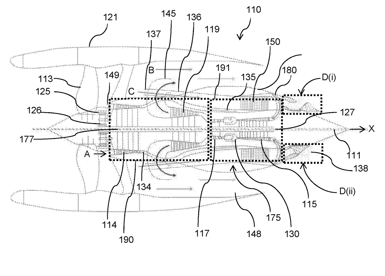
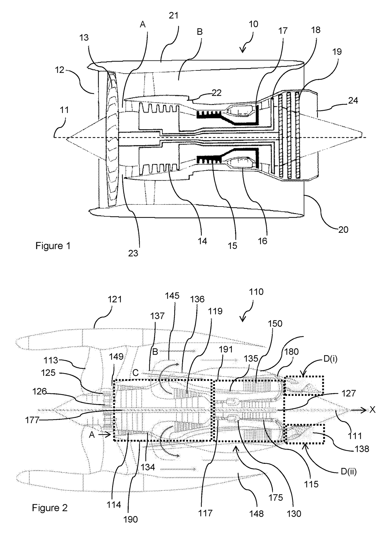
[0021]FIGS. 2 and 3 show a first gas turbine engine 110 in accordance with the present invention. The engine 110 comprises a ducted fan 113 provided within a fan nacelle 121 which defines a bypass passage 148. The fan 113 provides a propulsive air flow B which flows parallel to an axial direction X. A forward direction is defined by an axial direction anti-parallel to this direction.

[0022]The engine 110 further comprises an engine core 175. The core 175 comprises a first core module 190 comprising a first compressor in the form of a low pressure compressor 114 configured to draw core flow air A into the core 175 from an inlet 149 positioned downstream of the fan 113. The first core module 190 further comprises a first turbine in the form of a low pressure fan drive turbine 119 interconnected by a first shaft in the form of a low pressure shaft 177. The core 175 further comprises a second core module 191 comprising a second compressor in the form of a high pressure compressor 115 and...


PUM


Abstract

An aircraft gas turbine engine includes a fan arranged to be driven by a gas turbine engine core. The core includes a first core module including a first compressor and a fan drive turbine interconnected by a first shaft, and a second core module including a second compressor and a second turbine interconnected by a second shaft, the first and second core modules being axially spaced. The gas turbine engine further includes an intercooler arrangement configured to cool core airflow between the first and second compressors, the intercooler arrangement including a cooling air duct provided in heat exchange relationship with a compressor duct provided between the first and second compressors, the cooling air duct including a fan air inlet configured to ingest fan air downstream of the fan, wherein the cooling air duct includes a flow modulation valve configured to modulate air mass flow through the fan air inlet.

Description

FIELD OF THE INVENTION[0001]The present invention relates to a gas turbine engine, particularly to a gas turbine engine suitable for use on an aircraft, and an aircraft comprising a gas turbine engine.BACKGROUND TO THE INVENTION[0002]With reference to FIG. 1, a gas turbine engine is generally indicated at 10, having a principal and rotational axis 11. The engine 10 comprises, in axial flow series, an air intake 12, a propulsive fan 13, an intermediate pressure compressor 14, a high-pressure compressor 15, combustion equipment 16, a high-pressure turbine 17, and intermediate pressure turbine 18, a low-pressure turbine 19 and an exhaust nozzle 24. A nacelle 21 generally surrounds the engine 10 and defines both the intake 12 and a bypass exhaust nozzle 20.[0003]The gas turbine engine 10 works in the conventional manner so that air entering the intake 12 is accelerated by the fan 13 to produce two air flows: a first air flow A into the intermediate pressure compressor 14 and a second ai...

Claims


Application Information

Patent Timeline
IPC IPC(8): F02C7/143F02C3/04F02K3/06F02K3/115
CPCF02C7/143F02K3/06F02C3/04F05D2260/211F05D2220/323F05D2260/205F02K3/115Y02T50/60F02C3/145F02C7/042F02C7/057F02C7/18F02C9/18F02K3/075F02K3/077
Inventor BRADBROOK, STEPHEN J
Owner ROLLS ROYCE PLC
Why Eureka
Try Eureka