Cleaning Device
a cleaning device and cleaning technology, applied in the direction of cleaning process and apparatus, metal-working hand tools, brushes, etc., can solve the problems of difficult or impossible cleaning, difficult or impossible to reach by hand or with a brush or similar cleaning device,
- Summary
- Abstract
- Description
- Claims
- Application Information
AI Technical Summary
Benefits of technology
Problems solved by technology
Method used
Image

Examples
example 1
[0035]This example illustrates a configuration of an embodiment of a cleaning device of the present teachings.
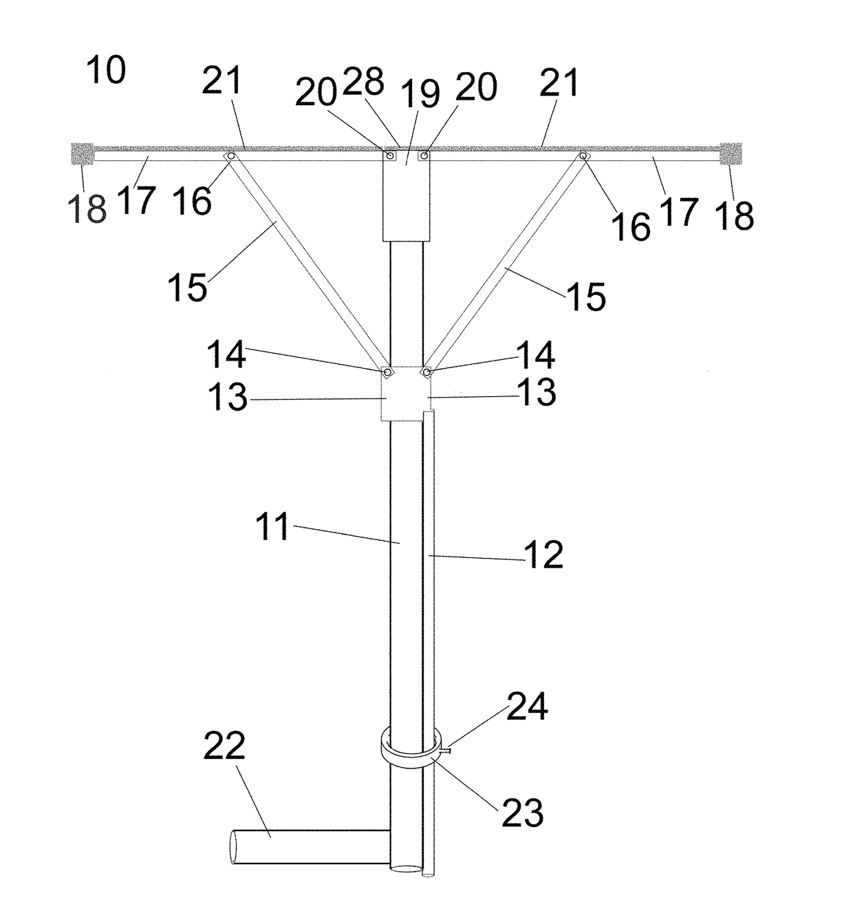
[0036]As shown in FIG. 1, a cleaning device 10 has a shaft 11. A hub 19 is located at one end of the shaft 11. A handle 22 is located at the opposite end of the shaft 11. 2 arms 17 are pivotally attached at pivots 20 to the hub 19. A runner 13 can slide along the shaft 11. A rod 12 is attached to the runner 13, and extends to approximately the length between the runner 13 and the base of the shaft 11 at the handle 22 when the arms 17 are maximally extended, or can be of another convenient length. A rod handle such as a flat handle or a loop (not shown) or other means for a user to grasp the rod 12 can be included on the rod 12 to facilitate pushing or pulling the rod 12 relative to the shaft 11. Means for reversibly securing the rod 12 to the shaft 11 are shown as a ring 23 that is attached to the shaft 11, and a set screw 24. The ring 23 includes a threaded opening for rece...
example 2
[0039]This example illustrates a configuration of an embodiment of a cleaning device of the present teachings.
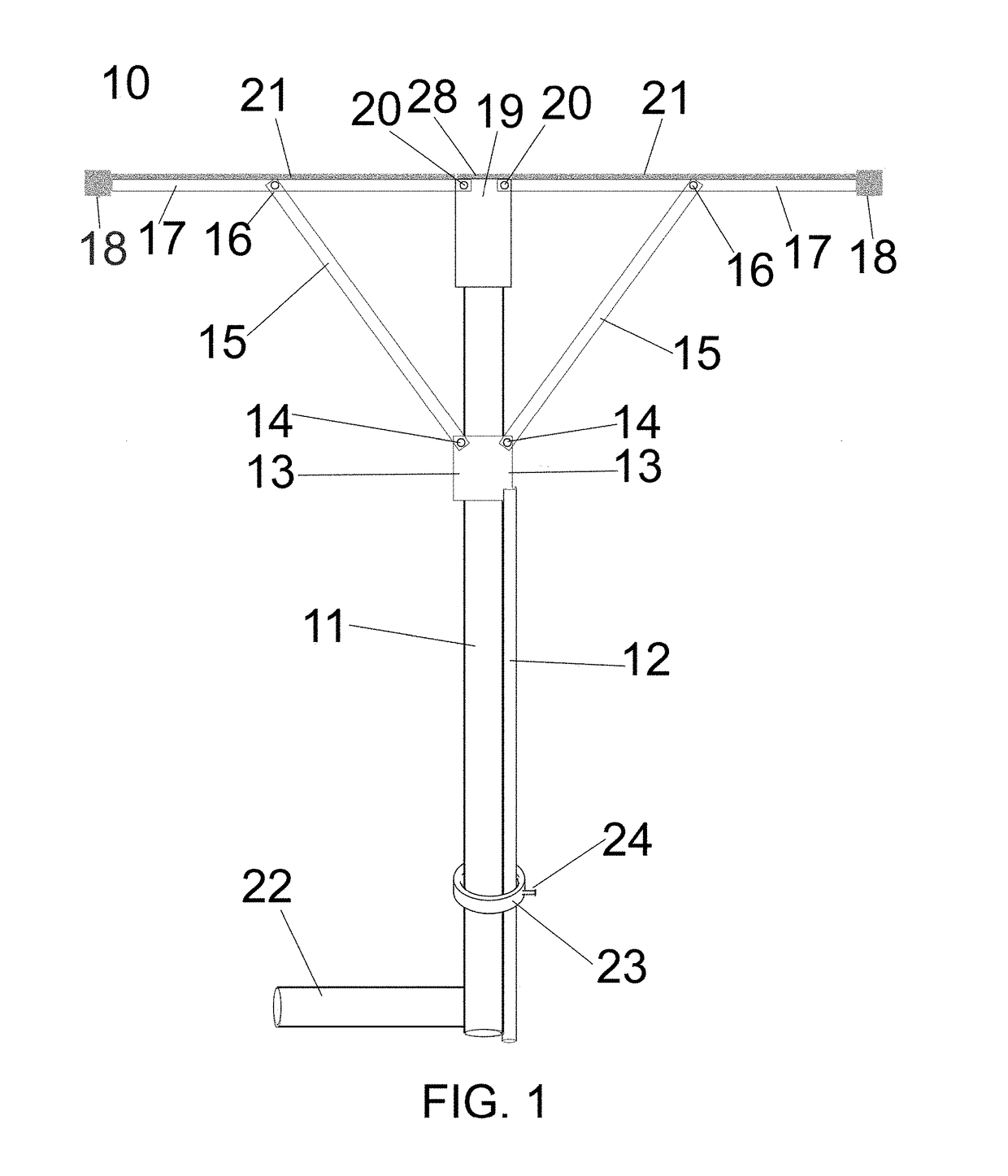
[0040]As shown in FIG. 2, a cleaning device 50 has a shaft 11. A hub 19 is located at one end of the shaft 11. In the configuration as shown, 2 arms 17 are each pivotally attached at a pivot 20. A runner 13 can slide along the shaft. A rod 12 is attached to a post 30 which in turn connects to the runner 13. The rod 12 can move parallel to the shaft H, and can be of a convenient length, such as, for example, a length sufficient to extend between the base of the shaft 11 at the handle 22 and the post 30 when the arms 17 are maximally extended. Means for reversibly securing the rod 12 to the shaft 11 are shown as a bracket 27, an extension 26, a guide ring 25, and a set screw 24. The rod 12 can move through the guide ring 25. The guide ring 25 includes a threaded opening for receiving the set screw 24. The set screw 24 can be tightened to secure the rod 12 in place, thereby mai...
example 3
[0043]This example illustrates a non-limiting use of a cleaning device of the present teachings.
[0044]Cleaning pads 18 with sponge surfaces 71 as shown in FIG. 3 are each attached to an arm 17 of a device 10 as illustrated in FIG. 1. A few drops of dish detergent are added to the sponge surfaces 71 and to wiping material 21 and 28. The set screw 24 is rotated counterclockwise to release the rod 12. Rod 12 is pulled back, resulting in arms 17 swinging against shaft 11. Set screw 24 is tightened by clockwise rotation, and the device 10 is inserted into a vase to be cleaned while holding handle 22. Set screw 24 is loosened by counterclockwise rotation, and rod 12 is then pushed until the arms are maximally extended. Set screw 24 is then tightened by clockwise rotation, securing the arms 17 in place relative to the shaft. The cleaning heads 18 can contact the inner walls, and the wiping materials 21 and 28 can contact the inner base of the vase. The user then moves the device relative t...
PUM
 Abstract
Description
Claims
Application Information
 - R&D
- Intellectual Property
- Life Sciences
- Materials
- Tech Scout
- Unparalleled Data Quality
- Higher Quality Content
- 60% Fewer Hallucinations
Browse by: Latest US Patents, China's latest patents, Technical Efficacy Thesaurus, Application Domain, Technology Topic, Popular Technical Reports.
© 2025 PatSnap. All rights reserved.Legal|Privacy policy|Modern Slavery Act Transparency Statement|Sitemap|About US| Contact US: help@patsnap.com