
Ventilation system for improving indoor air quality, HVAC system comprising the same and process thereof

a ventilation system and indoor air technology, applied in ventilation systems, heating types, instruments, etc., can solve the problems of irritating the respiratory system, affecting and affecting the health of the human body in the long term, so as to improve the air quality of the indoor spa

Active Publication Date: 2017-12-14
HANGZHOU LONG BEACH TECH CO LTD
View PDF0 Cites 36 Cited by
  • Summary
  • Abstract
  • Description
  • Claims
  • Application Information

AI Technical Summary

Benefits of technology

The present invention is a ventilation system that improves air quality in indoor spaces by measuring PM 2.5 particles, CO2 level, and TVOC level in real-time. The system includes an air blower that introduces outdoor air into the indoor space, and a control circuit that continuously adjusts the air blower's speed or torque based on the measured sensors' values. The resultant output signal ensures that the air blower operates at the optimal speed for each individual sensor, which in turn helps to improve air quality and promote healthy indoor environments.

Problems solved by technology

These nanoparticles may be damaging to the cardiovascular system, as they can pass through cell membranes and migrate into other organs, including the brain.
Although not acutely toxic, anthropogenic VOCs are harmful to human health in long term.
Ground-level ozone may harm lung function and irritate the respiratory system.
Exposure to ozone and its precursor is linked to premature death, asthma, bronchitis, heart attack, and other cardiopulmonary problems.
Long-term exposure to ozone may increase risk of death from respiratory illness.
Ozone can also be present in indoor air pollution, partly as a result of electronic equipment such as photocopiers.
Because of the strongly oxidizing properties of ozone, ozone is a primary irritant, affecting especially the eyes and respiratory systems and can be hazardous at even low concentrations.
However, inadequate oxygen supply may cause generalized hypoxia, the symptoms associated with which range from fatigue, numbness, tingling of extremities, to nausea and anoxia.

Method used


Image

  • Ventilation system for improving indoor air quality, HVAC system comprising the same and process thereof
  • Ventilation system for improving indoor air quality, HVAC system comprising the same and process thereof
  • Ventilation system for improving indoor air quality, HVAC system comprising the same and process thereof

Examples


Embodiment Construction

[0030]In the following description, for the purposes of explanation, numerous specific details are set forth in order to provide a thorough understanding of the present invention. It is apparent, however, to one skilled in the art that the present invention may be practiced without these specific details or with an equivalent arrangement.

[0031]Where a numerical range is disclosed herein, unless otherwise specified, such range is continuous, inclusive of both the minimum and maximum values of the range as well as every value between such minimum and maximum values. Still further, where a range refers to integers, only the integers from the minimum value to and including the maximum value of such range are included. In addition, where multiple ranges are provided to describe a feature or characteristic, such ranges can be combined.

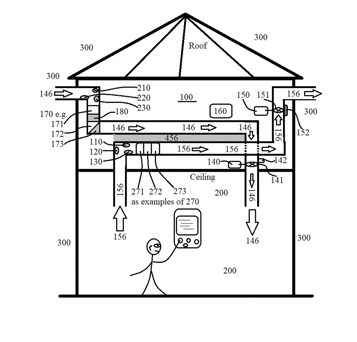
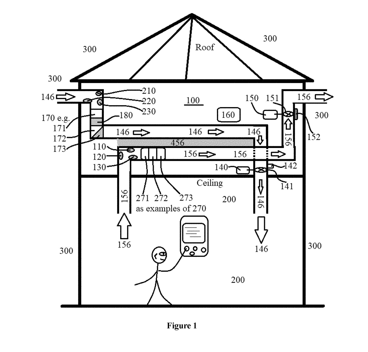
[0032]Referring to FIG. 1, an exemplary residential building includes a roof, a ceiling, and an indoor space 200. Installed between the ceiling and the roof...


PUM


Abstract

The present invention provides a ventilation system for improving air quality of an indoor space. The system includes sensors for measuring PM2.5 particle level P, CO2 level C, and TVOC level T in the indoor space. A control circuit is configured to receive P, C and T values and generate an output signal Vout according to a specific algorithm, which in turn controls speed-variable EC motors that drive ventilating fans. The invention exhibits numerous technical merits such as lower energy consumption, programmable operation, high efficiency, and lower noise, among others.

Description

CROSS-REFERENCE TO RELATED APPLICATIONS[0001]This non-provisional application expressly claims the benefit of priority under the Paris Convention based on Chinese Application No. 201610437764.6, filed on Jun. 8, 2016, the entire disclosures of which is incorporated herein by reference.STATEMENT REGARDING FEDERALLY SPONSORED RESEARCH OR DEVELOPMENT[0002]Not applicable.NAMES OF PART S TO A JOINT RESEARCH AGREEMENT[0003]Not applicable.REFERENCE TO AN APPENDIX SUBMITTED ON COMPACT DISC[0004]Not applicable.FIELD OF THE INVENTION[0005]The present invention generally relates to a ventilation system, a HVAC system comprising the ventilation system, and a process of using the ventilation system for improving indoor air quality. Although the invention will be illustrated, explained and exemplified using a residential building, it should be appreciated that the present invention can also be applied to other fields, for example, industrial buildings, laboratories, single family homes, apartment...

Claims


Application Information

Patent Timeline
IPC IPC(8): F24F11/00G01N1/26
CPCF24F11/0017G01N1/26F24F11/0086F24F2110/20F24F2110/50F24F11/89F24F2110/00F24F11/30F24F2110/10F24F11/79F24F3/16F24F7/007F24F12/001F24F13/24F24F13/28F24F2013/247F24F2110/70F24F2110/64F24F2110/12F24F2110/52F24F2110/22F24F8/40F24F8/10F24F11/77F24F12/006F24F11/74Y02B30/56Y02B30/70
Inventor ZHANG, WEICHEN, ZHAOFENG
Owner HANGZHOU LONG BEACH TECH CO LTD
Learn More